Download
1 / 31
310 likes | 444 Views
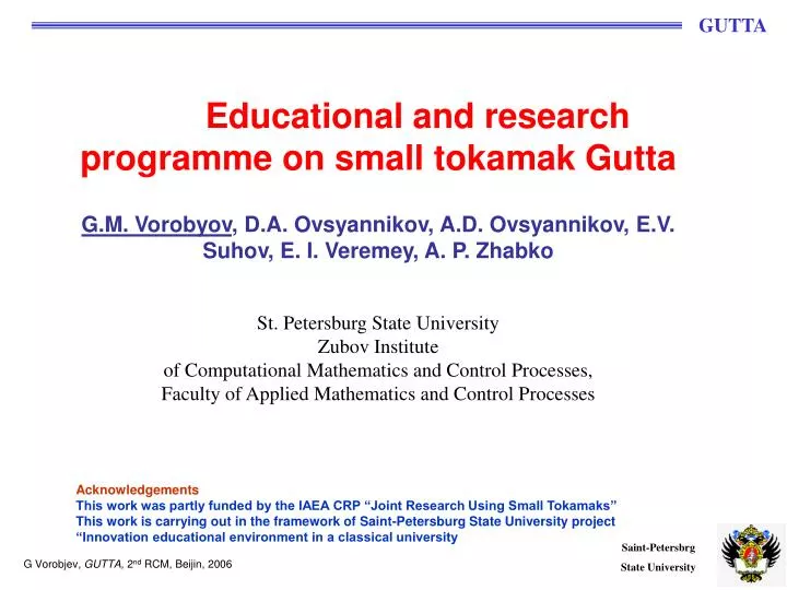
Educational and research programme on small tokamak Gutta G.M. Vorobyov , D.A. Ovsyannikov, A.D. Ovsyannikov, E.V. Suhov, E. I. Veremey, A. P. Zhabko St. Petersburg State University Zubov Institute of Computational Mathematics and Control Processes,

E N D
Educational and research programme on small tokamak Gutta G.M. Vorobyov, D.A. Ovsyannikov, A.D. Ovsyannikov, E.V. Suhov, E. I. Veremey, A. P. Zhabko St. Petersburg State University Zubov Institute of Computational Mathematics and Control Processes, Faculty of Applied Mathematics and Control Processes Acknowledgements This work was partly funded by the IAEA CRP “Joint Research Using Small Tokamaks” This work is carrying out in the framework of Saint-Petersburg State University project “Innovation educational environment in a classical university G Vorobjev, GUTTA, 2nd RCM, Beijin, 2006
GUTTA, IOFFE, USSR (1980-1986) GUTTA was one of the first attempts to built a spherical tokamak, G.M. Vorobyev et al, Ioffe Institute, 1980-86 Main parameters: major radius R, cm 16 minor radius a, cm 8 aspect ratio A 2 vessel elongation k 2 toroidal field, T 1.5 plasma current Ip, ka100 GUTTA at Ioffe Institute, 1984 GUTTA is now fully operational at St. Petersburg State University, Russia G Vorobjev, GUTTA, 2nd RCM, Beijin, 2006
Scientific scope and Working Plan for the 2nd year of the Project include: • Upgrade Data acquisition and processing systems • New Plasma diagnostics • Plasma control • Measuring of plasma characteristics, testing of different control codes, experiments on creating vertical-unstable plasma column and controlling such configuration. • Tokamak startup studies • Heating of plasma (ECRH), in collaboration with T-10. • Education program for undergraduate and postgraduate students. • University tokamak “MINI” design studies G Vorobjev, GUTTA, 2nd RCM, Beijin, 2006
Upgrade to the Data acquisition and processing systems: • Computer-based data acquisition system was set up, tested and calibrated. It consists of 96 fast ADC. • This system allows to collect all experimental data with high time resolution (500kHz). G Vorobjev, GUTTA, 2nd RCM, Beijin, 2006
New Plasma diagnostics • New optical diagnostics, SpectraPro high-resolution spectrometer (SP-2358i)with attached high-speed detector (CMOS pco.1200hs), has been commissioned. It includes a direct digital grating scan mechanism with full wavelength scanning capabilities. • Detector is equipped with 1280х16 pc2 CMOS camera and can process 40000 spectrum measurements per second. Additionally, intensity of fixed spectral line can be measured with photomultiplier attached to the second output of the spectrometer. • Experiments with 48-channels electro-magnetic diagnostic for plasma shape reconstruction have started. G Vorobjev, GUTTA, 2nd RCM, Beijin, 2006
Optical diagnostics Spectrograph SpectraProSP-2358: Specifications (1200g/mm Grating): Focal length: 300mm Aperture Ratio: f/4 Optical Design: Imaging Czerny-Turnerwith original polishedaspheric mirrors Optical Paths: 90° standard, 180° andmulti-port optional Scan Range: 0 to 1400nm mechanical range Operating Range: 185nm to the far infraredwith available gratings andaccessories Resolution: 0.1nm at 435.8nm Dispersion: 2.7nm/mm (nominal) Accuracy: ±0.2nm Repeatability: ±0.05nm Drive Step Size: 0.0025nm (nominal) Focal Plane Size: 27mm wide x 14mm high Spectrograph SpectraProSP-2358 pco.1200 hs CMOS detector G Vorobjev, GUTTA, 2nd RCM, Beijin, 2006
DATA ACQUISITION AND PROCESSING COMPLEX Control and diagnostics complex ADC boards Measurement channels number96 Input voltage range, В ±1,25 Input resistance, Ом 100 Sampling interval, μs 2,4,6,8,10,12,14,16 Input signals sampling5461 digital capacity 11bit + sign G Vorobjev, GUTTA, 2nd RCM, Beijin, 2006
Plasma control Plasma parameters required for control purposes were measured. Plasma response time on different control algorithms and vessel influence on control dynamics was measured. Vertical and horizontal feedback control systems were commissioned and tested. An experiment to create vertical-unstable plasma column and to control such configuration was carried out. G Vorobjev, GUTTA, 2nd RCM, Beijin, 2006
Horizontal feedback control system Main parameters of horizontal feedback control system: Power switch Voltage: 500V Current: 400A (1,2 kA in pulse) Frequency: 100 kHz Capacitor bank: Voltage: 450V Current: 39600 µF Charge and voltage control system Capacitor bank Start pulse Diagnostics Control signal Displacemet signal Power switch Integrator Comparator Magnetic flux changing Current Diagnostic coils Vertical field coil Vertival magetic field Magnetic flux Plasma column G Vorobjev, GUTTA, 2nd RCM, Beijin, 2006
Horizontal program control Main parameters of horizontal pre-program control system: Power switch: Voltage: 500V Current: 400A (1,2 kA in pulse) Frequency: 100 kHz Capacitor bank: Voltage: 450V Current: 39600 µF Digital controller: PIC 16F876 Communications: UART Charge and voltage control system Start pulse Capacitor bank Control signal Digital controller Power switch Settings Vertical field coil PC Plasma column G Vorobjev, GUTTA, 2nd RCM, Beijin, 2006
Vertical feedback control system Main parameters of vertical control system: Power switch: Voltage: 1000V Current: 200A (400 A in pulse) Frequency: 100 kHz Capacitor bank: Voltage: 1000V Current: 19800 µF Charge and voltage control system Capacitor bank Start pulse Diagnostics Control signal Summation unit Comparator Power switch Integrator Magnetic flux changing Displacemet signal Current Diagnostic coils Vertical field coil Vertival magetic field Magnetic flux Plasma column G Vorobjev, GUTTA, 2nd RCM, Beijin, 2006
Horizontal control system Flux w/o feedback Flux with feedback f/b request level f/b request f/b input f/b input Green- Magnetic flux through midplane Yellow- Control pulses Red-magnetic flux zero level White-control system threshold value Control feedback system OFF Green- Magnetic flux through midplane Yellow- Control pulses Red-magnetic flux zero level White-control system threshold value Control feedback system ON G Vorobjev, GUTTA, 2nd RCM, Beijin, 2006
Tokamak startup studies Non solenoid startup was investigated: - 300A achieved, duration 0.3ms, using 30kW 9.4GHz ECR. - Dependence of current amplitude on RF power and vertical fields was examined. Scenario with increasing toroidal field to provide constant stability factor (qa(t) = const) during current ramp-up was developed. G Vorobjev, GUTTA, 2nd RCM, Beijin, 2006
ECR discharge, experiment set-up. MICROVAWE POWER WAVE LENGTH 30mm FUNDAMENTAL RESONANCE at R = 16cm for B0=0.15T G Vorobjev, GUTTA, 2nd RCM, Beijin, 2006
ECR breakdown in pure Toroidal field b/d delay dependence on filling pressure Ha intensity dependence on filling pressure • breakdown delay increases at low pressure • no dependence of b/d delay on RF power at 5 - 20 kW • Ha intensity reduces with RF power • very similar results to what observed on START tokamak at Culham G Vorobjev, GUTTA, 2nd RCM, Beijin, 2006
Comparison of ECR b/d on START and GUTTA START: 2.45GHz ~1.0 kW, 3.5ms TF < 0.2 T, O- and X-mode launch GUTTA:9.4 GHz, 5 - 20 kW, 0.4 msTF ~ 0.15 T, O-mode launch • Ha intensity reduces with RF power • very similar dependence of Ha intensity on pressure • no pronounced maximum of Ha dependence at 5 kW – new result G Vorobjev, GUTTA, 2nd RCM, Beijin, 2006
ECR Discharge. Top, green – visible light; bottom, yellow – RF power at 900 in toroidal angle Ha Ha RF probe RF probe Gas pressure 1.75*10-4 torr Microwave power 20kW Gas pressure 1.75*10-4 torr Microwave power 20kW During ECR discharge with constant microwave power and some specific conditions (such as middle gas pressure, high microwave power, not very good conditioned wall) regular self-oscillations of visible light emission appear G Vorobjev, GUTTA, 2nd RCM, Beijin, 2006
ECR Discharge. Top, green – visible light; bottom, yellow – RF power at 900 in toroidal angle Ha RF probe RF probe Gas pressure 3.75*10-5 torr Microwave power 20kW Gas pressure 2.5*10-5 torr Microwave power 20kW At even lower filling pressure breakdown delay increases G Vorobjev, GUTTA, 2nd RCM, Beijin, 2006
ECR Discharge. UV lamp assisted b/d Top, green – visible light; bottom, yellow – RF power at 900 in toroidal angle Ha RF probe Gas pressure 2*10-5 torr Microwave power 4 kW Ultra-violet on – clear b/d Gas pressure 2*10-5 torr Microwave power 4 kW Ultra-violet off – no b/d Ultra-violet lamp assists breakdown at low pressure G Vorobjev, GUTTA, 2nd RCM, Beijin, 2006
Why there is a breakdown delay? • Common view is that when microwave power is ON, electron density rises to threshold value, then breakdown happens. This b/d delay depends on gas pressure, microwave power and poloidal fields. • To check, second RF pulse was applied with some delay to the first one • No b/d delay was observed during second pulse at same pressure, RF power, magnetic field (even if there was no light emission during 1st pulse) Ha Ha RF probe G Vorobjev, GUTTA, 2nd RCM, Beijin, 2006
Reverse current preionization Ha Uloop Top, yellow – visible light; bottom, green – Loop voltage • Reverse current preionization experiments were carried out. • Preionization using plasma current reversal is as effective as ECR preionisation (same light emission level) G Vorobjev, GUTTA, 2nd RCM, Beijin, 2006
ECR preionization with applied Uloop Breakdown does not occur without microwave power at Uloop ~15V Top, yellow – visible light; bottom, green – microwave power, red-loop voltage Ha Ha Uloop Uloop Standard breakdown order ECR breakdown not happens, however ohmic field breakdown occurs. 1 ms 4 ms Delay between ECR and ohmic field breakdown is increasing up to 4ms. Delay between ECR and ohmic field breakdown is increasing up to 1ms. G Vorobjev, GUTTA, 2nd RCM, Beijin, 2006
ECR preionization Top, yellow – visible light; bottom, green – microwave power, red-current in TF coils 15 ms 8 ms Ha Btor Delay between ECR and ohmic field breakdown is increasing up to 15ms. Toroidal field between breakdowns is absent. Delay between ECR and ohmic field breakdown is increasing up to 8ms. 50 ms 30 ms Delay between ECR and ohmic field breakdown is increasing up to 50ms. Toroidal field between breakdowns is absent. Delay between ECR and ohmic field breakdown is increasing up to 30ms. Toroidal field between breakdowns is absent. G Vorobjev, GUTTA, 2nd RCM, Beijin, 2006
ECR preionization experiments • Delay in light emission at constant microwave power during ECR discharge, ECR and Ohmic field breakdown depends not only on processes in vacuum chamber, but on vacuum vessel wall conditions • Preliminary cleaning methods, ultraviolet radiation before breakdown, ECR preionization (even without breakdown) affects these conditions. • Consequence of such influence stay for a long time, which is typical not for charged particles lifetime, but for chemical processes on vacuum vessel walls. G Vorobjev, GUTTA, 2nd RCM, Beijin, 2006
Heating of plasma (ECRH) • ECRH experiments, with RF power source with power 30kW and 9.4 GHz were carried out. • Experiment with RF power up to 200 kW is now under preparation in collaboration with T-10 team. G Vorobjev, GUTTA, 2nd RCM, Beijin, 2006
Education program for undergraduate and postgraduate students • Undergraduate students participated in computation of magnetic configurations, equilibrium and stability conditions and experimental verification of theoretical calculations on GUTTA tokamak and in control and data manipulation software developing. • Laboratory work ”Plasma equilibrium control in a tokamak” was prepared and tested. • Two graduate students and one post-graduate student participated in the 2nd JE at T-10 G Vorobjev, GUTTA, 2nd RCM, Beijin, 2006
University tokamak “MINI” design studies Main design features of tokamak “Mini” were chosen. Calculations have been performed to verify these parameters. Major radius, cm 20 Plasma current, kA 200 Minor radius, cm 10 Plasma density, cm-3 3·1014 Aspect ratio 2 Electron temperature, eV 200 Elongation 3 Ion temperature, eV 150 Toroidal magnetic field, T 2 Energy confinement time,ms 2 G Vorobjev, GUTTA, 2nd RCM, Beijin, 2006
Plasma Formation in CTF Inspired by Culham’s new CTF design with the use of Ferritic steel central rod, 1:5 (scale) model of the CTF central post has been installed in GUTTA We plan to use GUTTA tokamak for proof-of-principle demonstration G Vorobjev, GUTTA, 2nd RCM, Beijin, 2006
z measuring coils Plasma Formation in CTF: GUTTA 1:5 model Soft iron rod and Al imitation of TF coil (not shown in photo) Induction coils: 50Hz, 4A x 1000turns plasma measured flux structure • Flux measurements have been done with and without TF coil G Vorobjev, GUTTA, 2nd RCM, Beijin, 2006
V z, cm Plasma Formation in CTF: GUTTA 1:5 model • How much flux at midplane can be produced? • flux loss by factor of 5 due to iron saturation, some of it can still be used during ramp-up • solid TF coil requires radial cuts for flux penetration Coil signal (flux) vs distance from induction coil: red – without TF coil; black – with TF coil G Vorobjev, GUTTA, 2nd RCM, Beijin, 2006
Future plans Plasma modeling and control Development and verification of new mathematical models are scheduled. Improvement and adaptation of different control methods under control system capabilities will be performed. Development of control hardware is planned. Reverse current preionization Experiments on preionization with reverse current are scheduled. Dependenses on vertical, toridal, ohmic fields and RF power will be studied. Optical diagnostics Experiments to determine plasma temperature and density with optical diagnostics are scheduled. Outer magnetic surface shape reconstruction Tokamka Gutta is equipped with 48-channel electro-magnetic diagnostic for plasma shape reconstruction. Development, approbation and comparison of different mathematical methods of shape reconstruction are scheduled. Postgraduate students will participate in this activity. G Vorobjev, GUTTA, 2nd RCM, Beijin, 2006