Download
1 / 10
120 likes | 596 Views
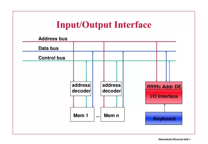
Input/Output Interface. Address bus. Data bus. Control bus. address decoder. address decoder. fffffffc Addr DE. I/O Interface. Mem 1. Mem n. Keyboard. How to do I/O. By “Polling” li $t1 0xfffffffc ;Interface address waitkey: lb $t0 0($t1) ;Poll Keybard

E N D
Input/Output Interface Address bus Data bus Control bus address decoder address decoder fffffffc Addr DE I/O Interface Mem 1 ... Mem n Keyboard
How to do I/O • By “Polling” li $t1 0xfffffffc ;Interface address waitkey: lb $t0 0($t1) ;Poll Keybard nop beq $t0 $r0 waitkey ;no key strike nop • + Very simple and fast • - Can’t do any useful work while waiting • - Only OK in a single process system, might miss data if other process takes over
External Interrupt Let the Interface generate an External Interrupt when data is available • + Access I/O Interface only when needed • + I/O handling is done by OS (Operating System) • I/O addresses can be “privileged” for SAFETY • + Data is never lost (if processor fast enough) • - Slower than “Polling” • We will address that problem later
Input/Output Interface Address bus Data bus Control bus CTRL[INT2]=keyboard strike fffffffc Addr DE I/O Interface Moore about: Buffered I/O “Intelligent Devices” etc. later. Keyboard
An External Interrupt Occurs • The “context” of the User program must be restored User Program Kernel Program . .. bne $t0 $r0 upp mfc0 $k0 $14 jr $k0 rfe add $t0 $t1 $t2 .. .
Multiple Processes User 1 User 2 User 3 Kernel .text .text .text .ktext Instructions .data .data .data .kdata Data
Time Slicing, Context Switch • On Each Timer Interrupt • Store the User program “Context” • Choose next User program (process) • Round robin process scheduling • Restore its “Context” • Pass control to User program
Process Control Block (PCB) • Resume Address (next PC for this process) • Global Data pointer ($gp) • Stack pointer ($sp) • All registers but $k0, $k1, $gp, $sp • $k0, $k1 might be trashed by the Kernel code • $gp, $sp stored in the PCB
Process Control Block PCB for Process p1 next_pc $gp $sp .text resume addr base for global data area for p1 .data top of user p1 stack .p1 stack $pc,$sp,$gp are initiated by the OS at “run” time
Where are the 28 registers? PCB p1 PCB p1 next_pc $gp $sp Let’s put them on the user program’s stack! next_pc $gp $sp And adjust the $sp $t0 $t1 … .. $t0 $t1 … .. .p1 stack .p1 stack