Download
1 / 31
310 likes | 444 Views
RAMP Common Interface. Krste Asanovic Derek Chiou Joel Emer. General Requirements. Provide a language agnostic environment that facilitates sharing of modules

E N D
RAMP Common Interface Krste Asanovic Derek Chiou Joel Emer
General Requirements • Provide a language agnostic environment that facilitates sharing of modules • Provide a modeling standard to facilitate the representation of time in the model target system that is independent of the host cycle time • Provide a reusable set of ‘unmodel’ services that can be used by different projects • Provide an underlying communication standard that can be used to specify standard interfaces • Facilitate the creation of a specific set of modules that can be shared and that communicate via standard interfaces
Key infrastructure components • Modeling core architecture • Modeling time • Implementing inter-module data communication • Simulation control and support infrastructure (unModel) • simulation control • communication to front-end or control processor • simulation support • stats, events, assertions, knobs... • Virtual Platform • Local memory access • Shared memory access • Host to FPGA communication channel
Target and Host RTL Model RTL Target RTL Unmodel RTL Platform RTL Host RTL
Translation from Target RTL to Model RTL • Start (conceptually) with final RTL • Partition design into units and channels • All inter-unit communication goes over channels • Channels have fixed latency • they are a systolic pipeline • latency set by what was mapped into the channel Unit Channel Representation as a bipartite graph
Translation from Target to Model (2) • Change representation of time from edges to tokens • Encapsulate data sent on an edge into a timing token • data on the timing channel is 1-1 mapping of original data signals • Replace each channel with a timing token channel • timing channel is a FIFO that transports timing tokens, e.g., A-ports • Convert unit to sink and source tokens by abiding by the following: • Unit waits for tokens on all inputs and reads them • Performs same computation as it did • Dequeues all input tokens • Sends a token on all outputs • Note: channel must be initialiized • Proof of equivalence to be provided
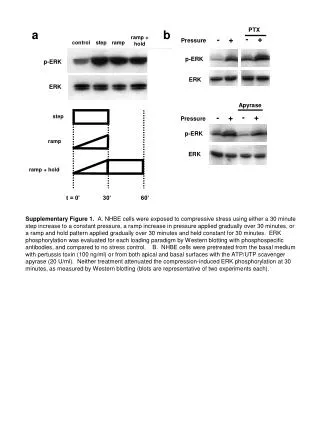
Distributed Timing Example D Unit B Target: Unit A Pipeline target channel implemented as distributed FIFO with at least L buffers Latency L Host: RDYs Start Start RDY D D UnitB Unit A ENQ DEQ Done Done DEQs
Retiming to simply host model • A shift register in the RTL can be converted into a timing token channel with the same latency. • A perfectly systolic computation in the RTL can be converted into a timing token channel with the same latency and the functionality of the pipeline must be moved into the 'unit'. In general any retiming that exposes a series of shift registers allows one to convert the shift registers into a timing token channel. 1 Multiply Multiply 2 1 Retimed Tokenized Target Tokenized Target
Definition: firing • A token-machine unit firing corresponds to the modeling of a single target machine cycle in that unit. • A token-machine unit firing comprises: • Reading one token from each input channel • Compute based on tokens and internal state • Writing one token to each output channel
Multi-cycle host units • The reads of all input tokens and writes of all output tokens can each be in different host cycles (while still reading each input and writing each output once each modelled cycle) • A firing can be implemented by reading all token inputs, computing and writing all token outputs using multiple host cycles • This is an example of a 'multi-cycle firing‘ and is what allows target cycle accounting to be independent of host cycles. 2 TokenizedTarget Host Multi-cycle host
Pipelined Host Units • Multiple firings of a single token-machine unit can be overlapped (e.g., pipelined) so long as: • the token firing rules are maintained and • any inter-firing data dependencies internal to the token-machine unit are also maintained. • Consequence is that multiple target cycles are in flight in a host unit at the same time.
Multiplexed host units • Firings from distinct target units can be multiplexed on a single host unit • The multiplexed unit has a distinct copy of state for each target unit being modeled • The multiplexed unit must read tokens from channels associated with the proper target unit. • This might be accomplished by multiplexing the channels themselves. Probably simple if all communication in each target unit is to the same token machine unit port Unit 1 Channel Unit 2 Tokenized Target Host
Basic channel interface A FIFO interface… • Send: • out notFull; • in [n:0] enq_data; • in enq_en; • Recv: • out notEmpty; • out[n:0] first; • in deq;
Channel Interface Variants Parallel channels (same source and dest and same latency) can be combined into a single timing channel - this reduces flow control overhead Communication on wide channels might be fragmented or packetized across multiple host cycles and internally reassembled into one token. Unit sees flow control at fragment level, but channel guarantees delivery at the token level.
Multiple clock domains Simple cross clock domain communication can be handled with rate matchers at fast end of channel. Unit A – 100 MHz Unit B – 66 MHz Channel
Channel No Message • Often as part of the process of abstracting a design into a model there is a situation where a communication is viewed as not happening… • For example, • To accommodate this situation an channel may include explicit transmission of a 'no message' token data enable
Units Servers Interface Layers Buffering Model domain unModel domain Flow Control Timing Services Direct + Client/Server One-wayClient/Server Point-to-pointOne-to-manyMany-to-one Logical Topology communication domain Point-to-pointRing TreeBus Physical Network Physical Link Intra-FPGA Inter-FPGACPU-to-FPGA dedicated channel TDM (multithreaded) channel
FAST connectors RDL channels “Soft connections” Units Multi-layer implementations Buffering Flow Control A-ports Timing Presentation Logical Topology Physical Network Physical Link
Logical Topology Semantics • Represents host-level inter-module communication • Supports both model and unmodel traffic • Latency may be more than one host cycle • Multiple patterns to be supported • One-to-one • One-to-many • Many-to-one • Must be expressible in multiple languages • Bluespec, Verilog...
Pattern Examples • 1-to-1 • Timing channels • 1-to-many • “run” command broadcast from controller • Many-to-one • assertion violation reporting
Logical Topology Endpoint Interface Endpoints are simply FIFOs Send: out notFull; in [n:0] enq_data; in enq_en; Recv: out notEmpty; out[n:0] first; in deq; Clocking endpoint has same clock as module connected to it cross host clock domain communication must be supported Conifguration Meta-information connection name connection direction connection pattern
Logical Topologies/Physical Interconnect Intra-FPGAlink Example: shared ring Bd 4 As 1 Ad 3 2 Asat station 1 communicates with Adat station 2 Bs Bsat station 2 communicates withBdat station 4
Units Servers Interface Layers Buffering Model domain unModel domain Flow Control Timing Services Connections One-wayClient/Server Point-to-pointOne-to-manyMany-to-one Logical Topology communication domain Point-to-pointRing TreeBus Physical Network Physical Link Intra-FPGA Inter-FPGACPU-to-FPGA dedicated channel TDM (multithreaded) channel
Physical Network Characteristics • Host-level communication fabric • Reliable transmission • Deadlock Free • Includes buffering for meeting above requirements • Additional buffering is provide at higher layers
Physical Link Interface Semantics • Host-level communication channel • FIFO-style interface • Decoupled input/output • Error-free (reliable delivery) • Uni-directional • Point-to-point • Packet description (TBD) • Indeterminate (but finite) latency
Units Servers Interface Layers Buffering Model domain unModel domain Flow Control Timing Services Connections One-wayClient/Server Point-to-pointOne-to-manyMany-to-one Logical Topology communication domain Point-to-pointRing TreeBus Physical Network Physical Link Intra-FPGA Inter-FPGACPU-to-FPGA dedicated channel TDM (multithreaded) channel
UnModel Support Services Run control Units can be commands to start, stop, etc… Dynamic parameters Units can be configured at runtime Statistics Unit can collect and report event counts Event logging Unit can log a series of events for each cycle Assertions Unit can do runtime checks of invariants and report violations
Service Organization Global Controller GlobalControl LocalControl StatController ParamController Stat DynamicParam Unit Host CPU
Servers and services interface • Service interface is implemented via separate input and output channels that handle requests and responses • Each input/output pair forms a service which implements multiple methods • Request / response is in-order for a single service • Synchronization between calls to different services must be provided by clients. • We provide serializability of operations.
Build process • Handling logical endpoint connections • Would like to avoid requiring parents to need to specify connections • Bluespec: use static elaboration, e.g., “soft connections” • Verilog: use TBD preprocessor • Who maps logical connections to physical networks? • Locally • Globally • 'Static' build parameters • 'Dynamic' run parameters