Download
1 / 42
490 likes | 1.56k Views
Energy Harvesting Bicycle Light. ECE 445 Senior Design Presented By: Jose Cortez Brian Roether Benjamin Andrews. Presentation Outline:. Introduction Hardware Design and Verification Assembly Final Testing Ethics Success and Challenges. Project Objective. Harvest vibration energy

E N D
Energy Harvesting Bicycle Light ECE 445 Senior Design Presented By: Jose Cortez Brian Roether Benjamin Andrews
Presentation Outline: • Introduction • Hardware Design and Verification • Assembly • Final Testing • Ethics • Success and Challenges
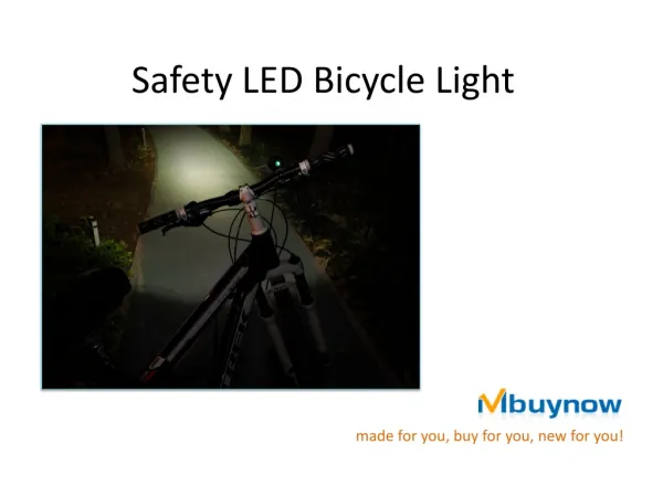
Project Objective • Harvest vibration energy • Use the energy generated by the suspension of the bicycle. • Energy that is normally wasted is harvested. • Make a self-sufficient warning light system • The warning lights must be bright enough to alert observers • Low power
Modifications Since the Design Review • Initial design specified that the linear generator would harvest the vibrations of the bicycle. • That system was unable to generate significant power and was re-designed to be connected into the suspension.
The Old Generator Very primitive Non-symmetrical output Poorly Modified Very heavy Fragile
The New Generator • Sturdy construction • Symmetrical and consistent output • Comparatively light weight • Compact size • Easily modified • Aesthetically pleasing
Linear Generator Theory Derived Equation of Voltage Output: Calculation for our generator: ≈ 2.5V
Linear Generator Materials Made with simple materials: PVC tubing 18 gauge copper magnet wire Wooden spool ends Snap rings N45 3 inch long cylinder neodymium magnet
Linear Generator Construction 3 inch long coil 3 inch diameter Additional PVC for magnet guide below generator Snap ring hold wooden ends onto generator
Linear Generator Power Maximum power output is between 95 and 150 mW.
Rectifier Design • The Rectifier produces a DC voltage from the AC input from the Linear Generator • The Rectifier steps up the voltage from the Linear Generator to a potential greater than the Battery Stack.
Rectifier Schematic Vout Vin+ DC Output Voltage Vin- Linear Generator GND The DC Output Voltage is approximately: Vout = 4*Vin-peak – 4*Vdrop => Vout = 4*Vin-peak , Vin-peak >> Vdrop
Rectifier Simulations Schottky Diode Vout = 7.5V 8V 6V Normal Diode Vout = 6V 4V 2V 0V 0 sec 0.5 sec 1.0 sec This is the response of the circuit with a 4Vp-p input voltage. Vout = 4*(2V) – 4*(.7V) = 8 – 2.8 = 5.2V (Normal Diode) Vout = 4*(2V) – 4*(.2V) = 8 - .8 = 7.2V (Schottky Diode)
Verification • The max output voltage is 7.31V which is in between the values from the calculation and the max output from the simulation. • Also it took the same amount of time to reach the maximum voltage, ~1 sec, as was found in the simulation.
Battery Charger Design Rectifier DC Output Voltage Divider Battery Stack • The battery charger works by allowing 100% of the power generated to go directly to the batteries. • When the batteries overcharge the MOSFET shorts out the rectifier and does not allow current to flow to the batteries.
Voltage Divider • The values for the voltage divider were determined by the following equation: • Where 3.4V is the threshold voltage and 3.7V is where the batteries first start to divert current.
Current Flow Simulation 60mA 50mA • This simulation shows proper operation of the circuit. • As the battery voltage climbs, the current is redirected through the MOSFET. MOSFET Current 40mA 30mA 20mA 10mA Battery Current 0mA 3.6V 3.7V 3.8V 3.9V 4.0V
Integrating the Rectifier and Battery Charger • The Rectifier and Battery Charger are connected via a large storage capacitor. • The storage capacitor acts as a low pass filter and helps to eliminate excessive ripple to the battery stack. Linear Generator Storage Capacitor (1000uF) Battery Stack
Simulation Verification 6 mA Battery Current 4 mA 2 mA MOSFET Current 0 mA -2 mA 0 sec .5 sec 1 sec This is the current flowing into the batteries when the batteries are operating their nominal voltage, 3.6V
Design Efficiency • Power Efficiency was determined by comparing the input power to output power. • The formula for determining power was: Input Voltage [VAC]
Alternative Battery Charger Designs • Zener Diode • 3.9V Zener diode was used to regulate the voltage into the batteries • Required too much current enter the breakdown region, ~50mA • Relay • The relay coil sank too much current and the capacitor was unable to charge over the batteries voltage.
Astable Multivibrator Circuit R and C set the frequency Rc sets the collector current 2N3904 npn BJT 0.5 Watt White LED Warning Lights Design
Warning Lights Design Calculations
Warning Lights Verification Oscilloscope measured output frequency was about 3.92 [HZ]. Although we did not get our theoretical frequency, it is very close to our prediction and it satisfies our needs.
Warning Lights Verification • Overall circuit current pull: • Measured overall current pull of circuit while connected to the DC power supply was about 3 [mA] at an input of 3.6 [VDC]. • The batteries are rated for about 2300 [mAh]. So this means that we can run circuit for 766 hours. • 2300 [mAh]/3 [mA] = 766. 67 [h]
Main Housing Waterproof cylinder shaped housing for linear generator, rectifier circuit, battery charging circuit and batteries.
LED Flashing Circuit Housing Clip can easily be removed with a screwdriver Clear weather proof casing
Linear Amplifier Necessary for maximum energy transfer 2.5 times increase in distance and speed travelled by the magnet Made from 1/8 inch aluminum bar and 3/16 inch steel rod Easily upgraded to handle more force
Final Testing Once all components were assembled and mounted to the bicycle, the bicycle was tested in several scenarios: Sidewalks Asphalt Gravel Bricks Bicycle Tricks
Ethical Concerns Components falling off the bicycle and causing an accident. Leverage system failure could cause front brakes to malfunction. High power magnet could potentially stick to the front braking system.
Successes Being able to harvest energy with linear generator. Amplifying the magnet’s travel through the linear generator. Passively amplifying the voltage output of the generator to a level higher than the batteries.
Challenges • Mechanical: • Attaching the system into the suspension of the bicycle. • Designing a lever system to amplify vibrations • Electrical: • Designing an extremely low power smart battery charging system.
Recommendations • Piezoelectrics • More expensive • More compact and generate more power • RF Power • Harvests ambient electro-magnetic energy • Average power 100mW
Questions and Answers Does anyone have any questions? We will answer them to the best of our ability.