Download
1 / 23
230 likes | 560 Views
Channel Control ASIC for the CMS Hadron Calorimeter Front End Readout Module. Ray Yarema, Alan Baumbaugh, Ahmed Boubekeur, John Elias, Theresa Shaw September 12, 2002. CCA Use in CMS. CCAs are used for processing both HPD and PMT signals

E N D
Channel Control ASIC for the CMS Hadron Calorimeter Front End Readout Module Ray Yarema, Alan Baumbaugh, Ahmed Boubekeur, John Elias, Theresa Shaw September 12, 2002 7th Workshop on Electronics for LHC
CCA Use in CMS • CCAs are used for processing both HPD and PMT signals • CCA provides control and interface for QIE ASICs which digitize charge input signals. • CCAs and QIEs are mounted on the CMS Hadron Calorimeter Front End Readout Module • CCAs and QIEs were designed at Fermilab 7th Workshop on Electronics for LHC
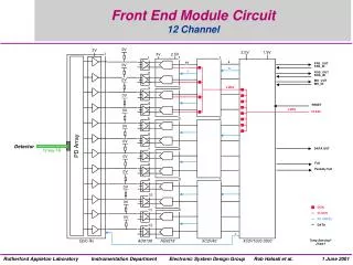
Front End Readout Module • Two QIE chips interface to one CCA chip • There are 3 CCA chips on a Front End Readout Module • 3 CCAs feed data to 2 GOLs 7th Workshop on Electronics for LHC
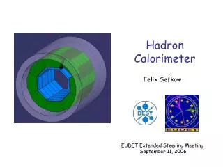
Hadron Calorimeter Front End Module 7th Workshop on Electronics for LHC
What is a QIE?(Charge Integrator and Encoder) • QIE digitizes input signal over a wide dynamic range • QIE operates in a 4 step pipeline mode • The data is output as a 2 bit exponent and 5 bit mantissa along with the time slice information which is referred to as Cap ID • QIE can be programmed to accept either positive (PMT) or negative (HPD) input charge 7th Workshop on Electronics for LHC
Primary Functions of CCA • Send individually programmable delayed clocks to each of the QIEs, to correct for time differences within the hadron calorimeter (58 nsec max) • Accept exponent and mantissa information from 2 QIEs, align the data and send the data to a gigabit serializer that drives an optical link 7th Workshop on Electronics for LHC
Provide RBX serial interface, similar to I2C, for programming features See that QIEs are operating in sync by checking QIE capacitor IDs Force QIE into fixed range instead of autoranging for test purposes Adjust QIE pedestal level to correct for HPD leakage Reset QIEs Place QIE in calibration mode Issue test pulse triggers of programmable polarity for either HPD or PMT Flag zero crossing counter check error Test pattern registers to check operation of DAQ Other CCA Features 7th Workshop on Electronics for LHC
CCA Connections • Figure on the right shows connections for 1 QIE feeding ½ of a CCA followed by the GOL • Chip address lines RBX_A are programmed by 6 hard wire connections on circuit board 7th Workshop on Electronics for LHC
Operation of CCA Blocks • RBX interface and registers • Delay Lock Loop for QIE clock adjustment • QIE data alignment and data formatting for GOL • Other miscellaneous circuits 7th Workshop on Electronics for LHC
CCA chip address is set by 6 hard wire connections on PCB RBX bus is a 2 wire communication interface which is similar to I2C All data is down loaded, 8 bits at a time, through RBX_DATA line with each RBX bus cycle RBX clock is intended to run at 100Kbits/sec RBX data is transferred either to or from the 1)Pointer Register or the 2) Data Register The Pointer Register points to 1 of 28 eight bit internal registers. Data Register contains data to be written or read from pointer address location The Pointer Register automatically increments after each data transfer to reduce chip communication overhead All registers designed with SEU tolerant latches to reduce SEU effects RBX Interface and Registers 7th Workshop on Electronics for LHC
Control Register Space and QIE Clock Adjustment 7th Workshop on Electronics for LHC
CCA Internal Control Registers • Control register – 1 register – sets various internal CCA controls and control settings for QIEs • Alignment Control registers – 2 registers, 1 for each of 2 QIEs – selects various timing options to permit channel operation with timing differences up to 58 ns. • Pedestal DAC Register – 1 register for 2 QIEs – 4 bits of adjustment for each of 2 QIE’s to correct for HPD leakage current changes • DLL Tap Select 0 Register – 1 register – choose clock delay for QIE0 in 1 ns increments from 0 to 25 ns • DLL Tap Select 1 Register – 1 register – choose clock delay for QIE1 in 1 ns increments from 0 to 25 ns 7th Workshop on Electronics for LHC
CCA Internal Control Registers(continued) • Test Bunch Counter Match Register -1 register - contains the Bunch Count at which a test pulse should be fired for the 2 QIEs, providing the “Enable Test Pulse” bit has been set in the Control Register • Test Pattern Registers – 20 registers – contains data or test patterns that are sent from the CCA through the GOL for 2 reasons: • To verify proper DAQ communication • To load data to a specific chip location and verify that the optical cable has been connected to the correct channel 7th Workshop on Electronics for LHC
Typical Download to CCA Via RBX Bus 7th Workshop on Electronics for LHC
Delay Locked Loop • Delay Locked Loop has 25 one nsec taps to provide fine control of QIE clocks • Each tap stage is comprised of 2 inverters 7th Workshop on Electronics for LHC
QIE Data Alignment and Transmission • Bits from Control Register set 4 muxs in Data Alignment block for proper data alignment • Cap IDs are checked for proper synchronization • Data Mux sends either Orbit message or QIE data at 40 MHz 7th Workshop on Electronics for LHC
Typical Data Transmission • When Bunch Crossing Zero is received, an Orbit Message is sent and at the same time the QIEs are reset with Cap ID=0. • QIE data is sent after the Orbit Message 7th Workshop on Electronics for LHC
Other CCA Circuits • Bunch Counter – 12 bit counter that starts at 0 and increments with the LHC clock. Before reset at next Bunch Crossing=0, counter value is compared to expected value in the Event Checker. Any errors are flagged. The BC value is also stored for transmission in Orbit Message • Test Pulse Trigger Comparator – Produces a Send_Test_Pulse signal when number in the Test Pulse Bunch Count Match Register equals the Bunch Counter number. Pulse is 1 cycle long. Polarity is settable through a bit in the Control Register. • Synchronizer – Synchronizes test pulses for the 2 QIE which have different clock delays so the test pulse occurs in the same time slice. Also Syncs QIE reset pulses. 7th Workshop on Electronics for LHC
CCA chip • Aligent 0.5 u CMOS process • 3.4 x 4.0 mm die • 128 QFP, 14 x 20 mm • Production run of 11400 parts (22800 channels) 7th Workshop on Electronics for LHC
Test Data • 500 parts packaged for testing • 21 separate tests in test program • 200 parts measured to set cuts in test program for power supply current (+/-15%) and delay time (+/- 2 ns) • 227 parts were tested with cuts • 222 good parts for yield of 97.8% • Remaining 10, 900 parts to be packaged 7th Workshop on Electronics for LHC
Conclusion • Production quantity of CCA has been received for the Hadron Calorimeter • All performance specifications have been met • The CCA has been successfully run on a Front End Module with the QIEs • The yield from testing the first 200 parts is very high. 7th Workshop on Electronics for LHC
Acknowledgements • The authors want to thank • Abder Mekkaoui for significant contributions throughout the development of the CCA • William Wester and Christian Gingu in the ASIC test group at Fermilab for the yield information that was used • Jim Hoff and Alpana Shenai for layout assistance • Al Dyer for his test assembly assistance 7th Workshop on Electronics for LHC