Download
1 / 57
570 likes | 690 Views
INTRO TO MPLS. CSE 8344 Southern Methodist University Fall 2003. Introduction. We will be discussing material from MPLS, Technology and Applications Read Chapters 1-5 and we will resume this topic after the MidTerm

E N D
INTRO TO MPLS CSE 8344 Southern Methodist University Fall 2003
Introduction • We will be discussing material from MPLS, Technology and Applications • Read Chapters 1-5 and we will resume this topic after the MidTerm • These notes will be based on the MPLS book plus some presentations from Cisco, Nortel, Juniper as well as Dr. Nair’s notes from last time.
Historical Perspective • X.25, Frame and ATM have proven themselves as a viable Layer2 transport technology • Virtual Circuits are nice for a number of reasons: • The route through the network is predictable • IP Networks can be built on Top • Just Like Ethernet but spread over the wide area. • The trend has been for the carrier to supply the layer 2 links and the enterprise to build IP on top. (“Keep the carrier out of my routing.”) • Often the enterprise will get a separate T1 or VC to the internet. • But IP routers are getting much bigger • This create lots of problems and questions.
Building big IP Networks • IP is beginning to dominate all other traffic • The need is for a cheap scalable IP network is the primary focus • 3 Different ways this could be built ….. 1) Use physical layer interfaces to connect IP routers Requires lots of physical layer interface cards in the router$$$$$$$$ Uses lots of bandwidth in backbone, because pipes may be sparsely filled. 2) Use a layer 2 mesh Use ATM or Frame Switches in the core to create a LOGICAL MESH at Layer 2 with fewer physical layer connections between routers OR..
Building big IP Networks (cont) • Build a mesh of routers This would use routers at both the edge of the network and the core Use fewer physical layer connections Lots of routers Potentially lots of router hops through the network Routers can be expensive and complicated Flooded route updates can consume time and bandwidth DataGram routing only SO…. Most operators chose to go with Option 2
How can we optimize an IP network over Layer 2 VCs? • ATM has many features that are NOT necessary to support IP • SVC’s not needed • Most of IP has been best effort (so far anyway) • QoS and admission control is overkill • CBR not needed • Early attempts to integrate ATM and IP were interesting: • LANE, ATMARP, MPOA, etc. • All were attempts to preserve both ATM and IP Doubly complicated because even more signaling and addressing schemes were required.
Issues • Price and performance • Scalability • Flexibility of routing functionality • Tight coupling between routing and forwarding algorithms
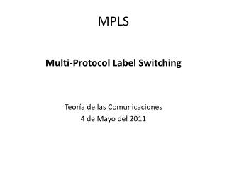
IP Over ATM ATM
Issues (IPOATM) • Exponential adjacencies • Means that more and more VCs must be built and managed to support the network. • If not, more hops • N^4 messages for topology changes • Changing the network can be a headache • Solution • Smart Label switching
Extending Router Functionality D A F C B E Plain old IP routing doesn’t allow us to route some traffic BD and some BE.
History • Cell switching router (CSR) • Toshiba • Mapped the IP signaling to control the ATM Network • Never really got off the ground • IP switching • Ipsilon • Strip the ATM hardware and use it as a router • Data driven connections through the network • Tag switching • Cisco • External control of Virtual Circuits (LSPs) • Not ATM specific
History (cont) • Multi-protocol Label Switching (MPLS) created in 1997 • Consisted of Tag Switching plus other input from Ipsilon, IBM (ARIS) and others. • Worked in the Internet Engineering Task Force (IETF) • IETF creates the Request For Comments (RFCs) that are quasi-standards
IP Switching • Introduced by Ipsilon • Significant innovations • General switch management protocol (GSMP) • Label binding protocol, Ipsilon flow management protocol (IFMP) • GSMP allows an ATM switch to be controlled by an “IP switch controller”
IP Switching Premise • IP over ATM models are complex and inefficient - involve running two control planes • ATM signaling and routing • IP routing and address resolution on top • In contrast IP Switching uses • IP component plus label binding protocol • Completely removes ATM control plane • Goal: To integrate ATM switches and IP routing in a simple and efficient way
Removing ATM Control Plane IP ATM MARS NHRP ARP PNNI Q.2931 ATM hardware • (a) IP over Standard ATM • (b) IP Switching IP IFMP ATM hardware (a) (b)
IP Switching Architecture • Switch controller • Control processor of the system • Uses GSMP to communicate with ATM switch • Runs IP routing and forwarding code • Default VC • To get control traffic before IP Switching is performed • Uses well known VCI/VPI value • Used for data that doesn’t have a label yet
IP Switch Architecture Switch controller Flow Classification and control To downstream switch To upstream switch Routing and forwarding IFMP GSMP GSMP Default VC Default VC Data VC Data VC Switch
Switching Basics • Relies on IP protocols • To establish routing information • To determine next hop • Flow classification and control module selects flows from incoming traffic • IP flow refers to a sequence of datagrams • from one source to one destination, identified by the ordered pair <source address, destination address> • can also refer to a flow at finer granularity, e.g., different applications between same pair of machines, identified by < source address, source port, destination address, destination port>
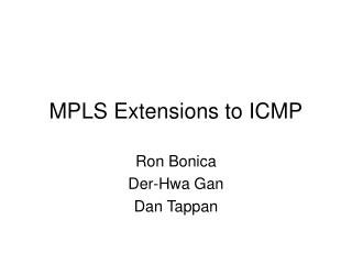
Flow Redirection • Redirection: Process of binding labels to flows and establishing label switched paths • Example: • data is flowing from A via B to C on default VC • B sends a redirect to A specifying flow y and the label (VPI/VCI) on which it expects to receive • If C issues a redirect to B for flow y, B forwards y on the VPI/VCI specified by C • Since same flow y enters B on one VC and leaves on another, B uses GSMP to inform its switching element to set up the appropriate switching path
Flow Redirection Redirect:Flow y VPI/VCI 3/57 Switch Controller B Switch B issues a REDIRECT message to switch A A A C Redirect:Flow y VPI/VCI 3/57 Redirect:Flow y VPI/VCI 2/22 Default VC Default VC Switch Element Switch Controller B C 3/57 Default VC Default VC Switch Element 3/57 2/22 Switch B and C redirect the same flow, allowing it to be switched at B
Ipsilon Flow Management Protocol (IFMP) • Designed to communicate flow to label binding information • IFMP is a soft state protocol • IFMP’s Adjacency Protocol: • Used to communicate and discover information about neighbors • Adjacency message sent as limited broadcast • IFMP’s Redirection Protocol • Used to send appropriate messages for flow-label bindings
Adjacency Protocol • To exchange initial set of information • ADJACENCY message encapsulated into IP datagram and sent to limited broadcast address • Also used to agree on the sequence numbers
IFMP’s Redirection Protocol • Different message types defined: • REDIRECT: used to bind label to a flow • RECLAIM: enables label to be unbound for subsequent re-use • RECLAIM ACK: Acknowledgement for RECLAIM message • ERROR: Used to deal with various error conditions • Common header format
IFMP Redirect Protocol Message Format IFMP REDIRECT message body
Encapsulation of Redirected Flows Encapsulation of IP packet on the default VC Encapsulation of IP packet on the redirected VCs
General Switch Management Protocol (GSMP) • GSMP is a master/slave protocol • ATM switch is the slave • Master could be any general purpose computer • The protocol allows the master to • Establish and release VC connections across the switch • Perform port management (Up, Down, Reset, Loopback) • Request Data (configuration information, statistics) • Allows slave to inform master of events such as link failure
GSMP (cont’d) • GSMP packets are LLC/SNAP encapsulated and sent over ATM link using AAL5 • GSMP Adjacency Protocol • Used to gain information about the system at the other end of the link and • To monitor link status • GSMP Connection Management Protocol • Used to ensure consistency between the GSMP master and slave • Specifies the QoS using a priority field
Design Goals • Adding functionality • Explicit routing • Improve scalability • Hierarchy of routing knowledge • Link layer independent • Not just ATM • Implemented in a variety of devices such as routers and ATM switches
Destination Based Routing • A TSR uses information from unicast routing protocols to construct its mapping between FECs and next hops • This mapping is used by the Tag Switching Control component for constructing the TFIB which is used for actual packet forwarding
Construction of TFIB • A local binding between the FEC and a tag • Takes a tag from the pool of free tags and uses it as an index in the TFIB to set the incoming tag entry • A mapping between the FEC and the next hop for that FEC (provided by the routing protocol(s) running on the TSR) • A remote binding between the FEC and a tag that is received from the next hop
Example A B if0 if1 if2 if1 E if2 if0 if0 if1 if2 if0 if2 if1 if0 TSR C D 192.6/16
Initial TFIB Entries For FEC 192.6/16
Behavior With Routing Change A B if0 if1 if2 if1 E if2 if0 if0 if1 if2 if0 if2 if1 if0 TSR C D Link Down
Hierarchical Routing • Scalability • Faster convergence • Fault isolation
Hierarchy of Routing Knowledge • All TSRs within a routing domain participate in a common intra-domain routing protocol and construct TFIB corresponding to destinations within the domain • All border TSRs or TERs within a domain and directly connected TERs from other domains also exchange Tag binding information via inter-domain routing protocol
Hierarchy (Cont’d) • To support forwarding,Tag switching allows a packet to carry several tags organized as a tag stack • At the ingress, a tag is pushed onto the tag stack, and at the egress a tag is popped off the stack
Hierarchical Routing Model Routing domain C Routing domain B Routing domain A V T X Y W Z TSR
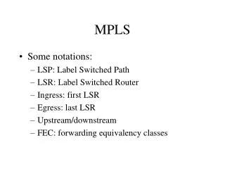
Label Stack Top of Stack 10 Top of Stack 2 2 Stack after processing in TSR T Stack after processing in TSR W TSR Z distributes label 2 to TSR W and TSR W gives label 5 to TSR T for the purpose of inter-domain routing
Multicast in Tag Switching • Selects the distribution tree based only on • tag carried in a packet • interface on which the packet arrives • TSR maintains its TFIB on a per interface basis • TSRs connected to a common sub-network agree among themselves on a common tag associated with a particular multicast tree
Multicast (Cont’d) • Partition the set of tags for use with multicast into disjoint subsets • Avoid overlap with the help of HELLO packets • TSR connected to a common sub-network and those which are a part of the same distribution tree elect one TSR that will create the tag bindings and distribute them • any TSR can join the group using the JOIN command
Multicast Model A B if0 D if0 if1 if2 if0 if0 TSR E F
RSVP With Tag Switching • RSVP supported with the help of a RSVP object - the tag Object • The tag object binding for an RSVP flow carried in the RSVP “RESV” message • The RESV message carries the tag object containing the tag given by a TSR and also information about the local resources to be used • The reservation state is refreshed once the flow is set up using the RESV message
Explicit Routes • Tag switching supports explicit routes with the help of Explicit Route Object • The object is carried in the RSVP “PATH” message • The tag information is carried in the Tag Object by the RSVP “RESV”
Tag Switching Over ATM • VCI field used as tag field • For stacks, use VPI • Cell interleave problem • VC merge • Different tags on the same path