Download
1 / 6
60 likes | 271 Views
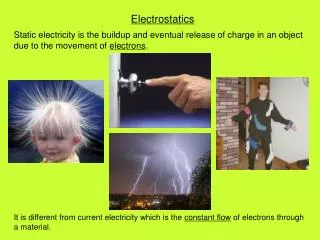
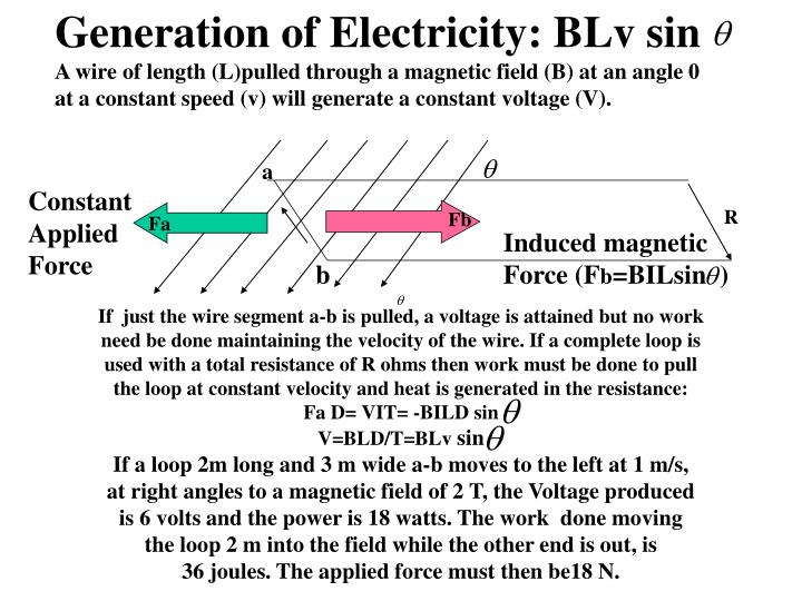
Generation of Electricity: BLv sin. A wire of length (L)pulled through a magnetic field (B) at an angle 0 at a constant speed (v) will generate a constant voltage (V). a. Constant Applied Force. R. Fb. Fa. Induced magnetic Force (F b =BILsin ). b.

E N D
Generation of Electricity: BLv sin A wire of length (L)pulled through a magnetic field (B) at an angle 0 at a constant speed (v) will generate a constant voltage (V). a Constant Applied Force R Fb Fa Induced magnetic Force (Fb=BILsin ) b If just the wire segment a-b is pulled, a voltage is attained but no work need be done maintaining the velocity of the wire. If a complete loop is used with a total resistance of R ohms then work must be done to pull the loop at constant velocity and heat is generated in the resistance: Fa D= VIT= -BILD sin V=BLD/T=BLv sin If a loop 2m long and 3 m wide a-b moves to the left at 1 m/s, at right angles to a magnetic field of 2 T, the Voltage produced is 6 volts and the power is 18 watts. The work done moving the loop 2 m into the field while the other end is out, is 36 joules. The applied force must then be18 N.
Generating electricity page 2 Another equation that can be used to calculate the voltage generated in pulling the loop through the field is: V= -^0/^t This can be derived from the diagram below: a b c V= x/t L Fa x d e f F d =work done = VIT=-BILd= Energy generated. V= - BL d/T= - B^A/^T The flux 0 through the loop is BA. 01 is the B times the area bounded by a-b-e-f. As the loop moves further into the field distance x (e to d) the additional area moving into the field is equal to the area bounded by b-c-d-e. Therefore ^0=B^A and V= - B^A/^T and V= -( 2 tesla)(3m)1m= -6 volts
Rotating the loop in a field. Now rotate this loop 90 degrees until it is parallel to the field in 2s A 3m B is still 2 tesla; 01= BA= 2(6) 02=0 since no field passes through the loop. V= -^0/^T= - 02-01/I= - (0-12)/2= - 6 volts 2m axis However, this voltage is an AVERAGE by the nature of deltaB/deltaT. If the work is calculated in rotating the loop 1/4 rotation in 2 s generating 6v (average) we find its not 36 joules as in the previous problem but 44joules! What is going on here? The flux through the the loop (B A cos O ) makes the following graph of flux: Since the Rate of Change of Flux equals the induced V, we can see that it is maximum at …a,b and c and zero at points d, e and f. OB e a b c 0 d f OB = (6)(2) Cos wt
12 Flux Slope = 9.42 2 Time Graph of 0=12 cos x becomes O=12 cos 0.7854 T since x=wT and w=pi/4 = 0.7854 Since V= - ^O/^T the generated voltage = - 9.42 volts
Relationship between the flux moving through the loop and the Induced Voltage (VL) Flux Volts 12 Flux O O VL -9.42 Induced voltage
Power= V2/R Volts