Download
1 / 114
1.15k likes | 1.2k Views
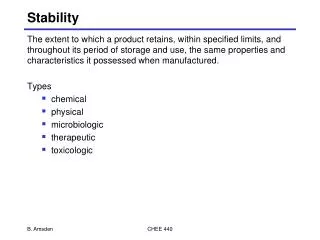
4.1 External Forces Acting on a Vessel. OVERALL STABILITY. In Chapter 4 we will study five areas: The concept of a ship’s Righting Moment (RM), the chief measure of stability. KG and TCG changes and their effects on RM.

E N D
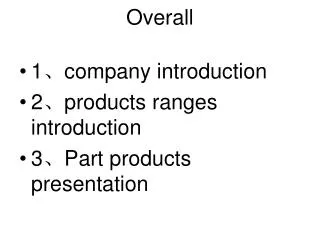
4.1 External Forces Acting on a Vessel OVERALL STABILITY • In Chapter 4 we will study five areas: • The concept of a ship’s Righting Moment (RM), the chief measure of stability. • KG and TCG changes and their effects on RM. • How Stability is effected by Damage to the Hull using the “Added Weight” method. • Effects of a “Free Surface”. • Effects of Negative GM on ship stability.
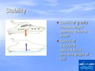
4.2 Internal Righting Moment • EXTERNAL FORCES cause a vessel to heel. Recall Force x Distance = Moment • External Moment can be caused by wind pushing on one side of the vessel and water resisting the motion on the other side. • Each distributed force can be resolved into a resultant force vector. The wind acts above the waterline and the water resistance acts below the waterline.
Internal Righting Moment MT f External upsetting force D s Righting Arm G WL Z f f F B F B Water resistance CL
Internal Righting Moment • The two forces create a couple because they are equal in magnitude, opposite in direction, and not aligned. • The couple causes rotation or heeling. • The vessel will continue to rotate until it returns to Static Equilibrium (i.e. an Internal Moment is created which is equal in magnitude and opposite in direction). Giving M=0.
Internal Righting Moment • Internal Forces create a Righting Moment to counter the Upsetting Moment of the External Forces. • The two internal forces are the weight of the vessel (s) and the resultant buoyant force (FB).
Internal Righting Moment • The perpendicular distance between the Weight and the Buoyancy Force vectors is defined as the RIGHTING ARM (GZ). • The moment created by the resultant Weight and the resultant Force of Buoyancy is defined as the RIGHTING MOMENT (RM). It may be calculated by: = = RM GZ GZ F s B
Internal Righting Moment Where: RM is the internal righting moment of the ship in ft-LT. s is displacement of the ship in LT. FB is the magnitude of the resultant buoyant force in LT. GZ is the righting arm in feet.
F C L The forces of wind- and the opposing force of the water below the waterline- will cause an external moment couple about the ship’s center of flotation. A ship in static equilibrium is affected by outside forces that will alter its state of equilibrium. MT Wind G Water Resistance
F B C L The ship reacts to this external moment couple by pivoting about F, causing a shift in the center of buoyancy. MT Wind G Water Resistance The center of buoyancy will shift because the submerged volume will change. Note that there is no change in weight or it’s distribution so there is NO change in the location of G!
F B C L The displacement force and the buoyant for are no longer aligned. The heeling over causes the creation of an internal moment couple. Because the location of B changes, the location of where the FB is applied also changes. Because G does not move, the location of the Δs force does not change. MT s G FB
Wind Water Resistance B C L The external moment couple causes the creation of the internal moment couple to oppose it. MT s G F FB As a result, the ship is now back into equilibrium, even as it heels over due to the wind force.
B C L The offset distance of the applied forces, GZ, is called the MOMENT ARM. The length of this moment arm is a function of the heeling angle,φ. We are concerned with the created internal moment caused by the offsetting of the ship’s weight and the buoyant force. Ds MT f G Z FB
In the case of the created internal moment couple, we have the two force,Ds and FB, acting over the distance GZ. RM = GZDs = GZFB Remember that a moment is created when a force acts at a distance from a given point. RIGHTING MOMENT The created moment is called the internal
Ds MT f G Z B FB C L This illustrates just one potential moment arm based upon one particular angle of φ. There are an infinite number of angles possible, therefore, an infinite number of moment arms that vary with the degree of heel, φ. If we can plot the heeling angle f versus the created moment arm GZ, we can create the Intact Statical Stability Curve.
4.3 Curve of Intact Statical Stability • “Curve of Intact Statical Stability” • or • “The Righting Arm Curve” • Shows the Heeling Angle () versus the righting arm (GZ). • Assumes the vessel is heeled over quasi- statically in calm water (i.e. external moments are applied in infinitely small steps).
This is a typical curve. Notice that it plots the angle of heel on the x-axis and the righting arm on the y-axis. The curve is in both the 1st and 3rd quadrants (the 3rd shows a heel to port). Typically only the curve showing a heel to starboard is shown as it is symmetrical.
Measure of Overall Stability Curve of Statical Stability Range of Stability Slope is a measure of tenderness or stiffness. Righting Arm - Dynamical Stability GZ -(feet) Maximum Righting Arm Angle of Maximum Righting Arm Angles of Inclination: (Degrees)
The above chart plots the data presented in the text on p. 4-6 an 4-7.
With φat 0 degrees, the moment arm is also is 0. The buoyant force and the ship’s weight are aligned. No moment is created.
As the angle of heel increases, the moment arm also increases. At 25 degrees, shown here, GZ is 2.5ft.
As the angle increases, the moment arm increases to a maximum… here it is 4ft. As φincreases beyond this point the moment arm begins to decrease and the ship becomes in danger of capsizing…
...Remember, the internal moment couple created here is in response to the external couple created by outside forces. At GZ max the ship is creating its maximum internal moment. If the external moment is greater than the internal moment, then the ship will continue to heel over until capsized.
The angle of heel continues to increase, but the moment arm GZ, and thus the internal moment couple, decreases.
The angle has now increased to the point that G and B are now aligned again, but not in a good way. GZ is now at 0 and no internal moment couple is present. Beyond this point the ship is officially capsized, unable to right itself.
Curve of Intact Statical Stability Caveats! • Predictions made by the Curves of Intact Statical Stability are not accurate for dynamic seaways because additional external forces and momentum are not included in the analysis. ”Added Mass” • However, it is a simple, useful tool for comparison and has been used to develop both intact and damaged stability criterion for the US Navy.
Curve of Intact Statical Stability • Typical Curve of Intact Statical Stability • Vessel is upright when no external forces are applied and the Center of Gravity is assumed on the centerline. (Hydrostatics) • As an external force is applied, the vessel heels over causing the Center of Buoyancy to move off the centerline. The Righting Arm (GZ) is no longer zero.
Curve of Intact Statical Stability • Typical Curve of Intact Statical Stability (cont.) • As the angle of heel increases, the Center of Buoyancy moves farther and farther outboard (increasing the Righting Arm). • The max Righting Arm will happen when the Center of Buoyancy is the furthest from the CG. This is max stability. • If the vessel continues to heel, the Center of Buoyancy will move back towards the CG and the Righting Arm will decrease.
Curve of Intact Statical Stability • Typical Curve of Intact Statical Stability (cont.) • Since stability is a function of displacement, there is a different curve for each displacement and KG. These are called the Cross Curves.
For all ships, there exists the CROSS CURVES OF STABILITY. • Like the Curves of Form, they are a series of curves presented on a common axis. • The x-axis is the ship’s displacement, Δs, in LT • The y-axis is the righting arm, GZ, in ft • A series of curves are presented, each representing a different angle of heel f By plotting the data from the Cross Curves of Stability for a given displacement, you can create an Intact Statical Stability Curve.
In the Cross Curves of Stability, the data is presented assuming that: KG = 0 (on the keel) This is, of course, not realistic. It is done this way so that the curves may be generalized for all drafts. Once the curve data is recorded and plotted, a sine correction factor must be applied, shifting the KG to its correct position in order to get the TRUE MOMENT RIGHTING ARM VALUE.
Cross Curves Example Righting Arm (feet) 30 degrees heel 5 10 degrees heel 2.5 At 2000 LT, the ship Has a RA of 2.5’ @10o Heel and 5’ @30o 0 1000 2000 3000 Displacement (LT)
Curve of Intact Statical Stability / “Righting Arm Curve”Assumes: • Quasi-static conditions • Given Displacement • Given KG Cross Curves of Stability • Since MT moves as a function of φ, Righting Arms are calculated for each φat regular intervals • Assumes a value of KG
4.4 Measure of Overall Stability • From the Curves of Intact Stability the following Measures of Overall Stability can be made: • Range of Stability • Maximum Righting Moment • Angle of Maximum Righting Moment • Dynamical Stability • Measure of Tenderness or Stiffness
Measure of Overall Stability • Range of Stability • The range of angles for which there exists a positive righting moment. • The greater the range of stability, the less likely the ship will capsize. • If the ship is heeled to any angle in the range of stability, the ship will exhibit an internal righting moment that will right the ship if the external moment ceases.
Measure of Overall Stability • Maximum Righting Moment • The largest Static Moment the ship can produce. • Calculated by multiplying the displacement of the vessel times the maximum Righting Arm. • The larger the Maximum Righting Moment, the less likely the vessel is to capsize.
Measure of Overall Stability • Angle of Maximum Righting Arm • The angle of inclination where the maximum Righting Arm occurs. Beyond this angle, the Righting Arm decreases. • It is desirable to have a larger maximum angle so that at large angles of heel in a rolling ship the righting moment will continue to increase.
Measure of Overall Stability • Dynamical Stability: • The work done by quasi-statically rolling the ship through its range of stability to the capsizing angle. • Can be calculated by the equation: . This is equal to the product of the ship’s displacement with the area under the Curve of Intact Statical Stability. • Not shown directly by the Curve of Intact Statical Stability. • Does not account for the actual dynamics, because it neglects the impact of waves and momentum.
Measure of Overall Stability • Measure of “Tenderness” or “Stiffness” • The initial slope of the intact statical stability curve indicates the rate at which a righting arm is developed as the ship is heeled over. This slope is GM! • A steep initial slope indicates the rapid development of a righting arm and the vessel is said to be stiff. Stiff vessels have short roll periods and react strongly to external heeling moments. • A small initial slope indicates the slower development of a righting arm and the vessel is said to be tender. Tender vessel have longer roll periods and react sluggishly to external heeling moments.
Step #3. Draw the curve, using φas x-axis, and GZ as y-axis Example: Plot the Intact Statical Stability Curve for an FFG-7 displacing 5000LT Step #1. From the Cross Curves of Form, find the 5000LT displacement value on the x-axis. Step #2. Record the righting arm value for each curve, from φ= 0 to 80 degrees
Intact Statical Stability Curve for FFG-7 @Ds = 5000LT … But a correction must still be made!!
Example Problem The Statical Stability curve applies to a ship with D=3600LT. The ship is being pulled sideways into a 10° list by a tug attached to the ship 10ft above the Waterline. How much force is the tug applying to the tow line?
F=10° FTug 10ft F G B Water Resistance FB D Example Answer RM=GZΔ=1.2ft×3600LT=4320ft-LT Upsetting Moment from Tug=FTug×10ft=RM (in static equilibrium) FTug=4320ft-LT/10ft=432LT
4.5 Effect of a Vertical Shift in the Center of Gravity on the Righting Arm In the Cross Curves of Stability, the data is presented assuming that: KG = 0 (on the keel) This is, of course, not realistic. It is done this way so that the curves may be generalized for all drafts. Once the curve data is recorded and plotted, a sine correction factor must be applied,shifting the KG to its correct position in order to get the TRUE MOMENT RIGHTING ARM VALUE. • Must Apply a Sine Correction if: • Using the Curve of Intact Statical Stability to correct for G not being located at K • Correcting the Curve of Intact Statical Stability for vertical movements of G
Wind F Water Resistance B C L The external moment couple causes the creation of the internal moment couple to oppose it. MT s G FB External Moment Couple = Internal Moment Couple
Z0 B1 C L When the ship heels over, the center of buoyancy, B, shifts. The shift creates a distance or “moment arm”. MT f G0 G0Z0 = Moment Arm
B1 G0 Z0 C L For values taken from the Cross Curves of Stability, G0 is at the keel... MT f G0Z0 = Moment Arm This value is recorded as G0Z0, the Initial Moment Arm.
Z0 B1 KG KG forms a similar triangle that gives the value for the SINE correction C L The KG value for the ship is given… this is the ACTUAL G position from the keel... MT f Gv G0
Sin f = opp hyp opp =correction factor hyp = KG Sine Correction factor = KG Sin f
Z0 B1 KG C L Sin Correction = KG Sin f MT f Gv G0
Z0 Zv B1 KG C L MT f Gv G0 GvZv = G0Z0 - KG sinf