Download
1 / 32
320 likes | 477 Views
Accuracy Improvement for physical robot. Gal Lerman , Dorin Ben- Zaken. The Project. The goal is to improve the accuracy of a robot. Based on a Motion Planning workshop for physical robots. Software improvements to the robot driver. Additional sensors supported by extra hardware.

E N D
Accuracy Improvement for physical robot Gal Lerman, Dorin Ben-Zaken
The Project • The goal is to improve the accuracy of a robot. • Based on a Motion Planning workshop for physical robots. • Software improvements to the robot driver. • Additional sensors supported by extra hardware.
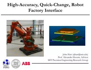
The Workshop • We have a computer controlled robot. • The robot maneuvers in an obstacle filled room. • The robot starts at a certain position and must reach a target position.
Just kidding…The iRobot Create • Two wheel differential drive robot. • Based on the well known Roomba vacuum cleaner.
The iRobot create • Left and right wheels are controlled separately. • Built-in sensors: • Left and right bumpers (know when the robot collides). • Wheel encoders (measures the number of wheel revolutions). • Lacking a high-quality distance sensor…So we added our own.
Encoder Inaccuracy Reasons • Wheel slippage counts as movement • Finite encoder resolution results in round-up errors • Errors are accumulated over distance – the greater the distance the bigger the error
Distance sensor Workshop Architecture Analog out Bluetooth RS 232 BAM
Robot Driver • Communication between the robot and the PC is done by serial communication over Bluetooth. • The robot driver sends command packets complying to the robot’s protocol. • The robot sends packets containing sensor data every 15ms. • Also implemented a simulator driver (using a shared interface).
Scene Loader • Scenes contain information about: • The bounding box of the room. • Obstacles. • Robot start and goal positions. • Scenes are loaded from files.
Scene Solver • A general interface for solving the motion planning problem. • Uses the PRM (Probabilistic Roadmap) algorithm: • Samples random free positions in the room. • Builds a graph by connecting near positions. • Reduces the problem to a shortest-path in graph problem.
Graphical User Interface (GUI) • A user interface for interacting with the system. • Also shows sensor data, roadmap and more. User Interface Scene Loader Robot Mover Scene Solver Interface Robot Driver Interface Physical Robot Driver Simulator Robot Driver PRM Scene Solver
Dynamic Obstacles • We added a remote-controlled Roomba to act as a dynamic obstacle. • Distance sensor is used to detect the Roomba. • Requires algorithm modifications: • When detecting a dynamic obstacle we add a temporary static obstacle. • Update the roadmap graph so that colliding edges are removed. • Re-plan using the new roadmap
Robot Competition • Two PCs controlling different robots. • Another PC acting as referee and coordinates between them. • First robot to reach its destination wins. • Communication over TCP.
Lack of accuracy demonstration • video
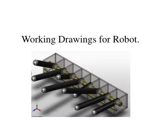
PC running robot’s motion path software Zigbee Communication XBee module XBee on USB dongle Original Project Architecture RS 232 Arduino microprocessor Gyroscope Accelerometer RS 232 iRobot create
Original Project Architecture - limitation • Robot response to command isn’t reliable - Robot freezes a lot • Other developers in the community complained about Xbee reliability in full duplex high packet rates scenarios • iRobot Command Module is a microcontroller designed for iRobot Create, in hind sight perhaps it was better to use it instead of Arduino
Analog out iRobot create Gyroscope D/A PC running robot’s motion path software Arduino microprocessor RS 232 Project Architecture Based on Workshop BAM Bluetooth Accelerometer Analog out Distance sensor Digital out * (*) Here we use Time Division Multiplexing on the 3 sensor data streams
Project Architecture Based on Workshop - cont • Xbee free architecture • Reuse of BAM as proven communication channel between robot and pc • Ardunio interfaces with the sensors and converts their data to n digital bits • D/A converters Arduino digital output to robot’s analog input • Time Division Multiplexing to transfer 3 sensor data stream using 1 analog input in the robot • Full use of the robot’s 4 digital inputs • 2 name bits – naming the sensor data • Start, Stop bits to solve Arduino-Robot synchronization problem (packet containing gyro’s name with distance data)
Project Architecture Based on Workshop - limitation • Only 8 bit D/A available in TAU where we needed at least 9 (8 bits for angle [0,180] and 1 bit for sign) • Complex architecture • A simpler idea came to mind…
Gyroscope Final Project Architecture PC running robot’s motion path software XBee on USB dongle Arduino microprocessor Gyro packets XBee Bluetooth Bluetooth Sensor data Power Commands iRobot create RS 232 BAM Analog out Distance sensor
Final Project Architecture - cont • PC has 2 serial connections • Xbee channel from Arduino • BAM channel to/from Robot • Xbee back in action but in only one sided communication and only sensor data to PC • Reuse of BAM as proven communication channel between robot and PC
Accelerometer limitation • Double integration to get location data from acceleration causes massive accumulation of errors • Tilt of the sensor is interpreted as movement • Mobile Robot Positioning – Sensors and Techniques by J.Borenstein, H.R. Everett, L. Feng and D.Wehe.
Software improvements • Wait angle command • Specify desired degrees and let the robot stop after executed • Requires to stop the sensor stream before command is lunched and resume it after command executed • Combine angle reading from robot’s odometry and gyroscope to get a more accurate angle
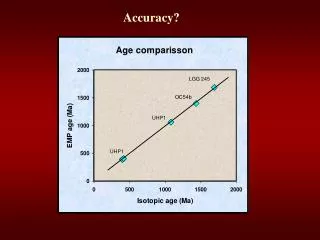
UMBmark – Odometry calibration • Based on a University of Michigan article from 1994 • Designed to correct systematic odometry errors • Systematic errors are caused by • Inaccurate wheel base • Inaccurate wheel radius • Calculates alpha and beta • α - the error in degrees when the robot tries to turn 90 degrees • β – the angle in degrees the robot has veered off a straight path after running the straight line
UMBmark – Odometry calibration cont • Correct α by turnAngle= requestedTurnAngle*(90/(90-α)) • Correct β by driving in an arc instead of straight line. Arc with radius of R = (L/2)/ β) • We couldn’t use it because of drive-with-radius command is limited to only 2m radius
Results - cont • video
Conclusions • Wait angle accounts for most of the accuracy improvement • No distance accuracy improvement because of accelerometer sensor’s limitations • Possibly better to use a laser sensor instead of accelerometer • Wait distance would probably improve the distance accuracy greatly, but at the cost of loosing response to dynamic obstacles
Thank you • Questions?