Download

1 / 16
160 likes | 263 Views
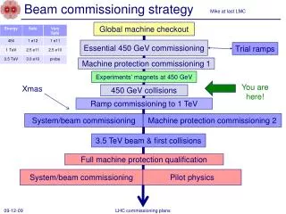
TE EPC. Drive beam magnets powering strategy. OUTLINE : Suggestion of a powering strategy for the drive beam quadrupoles in the main Linac, Calculation of the power losses in the cables, Estimation of the costs of the cabling and converters with possible reductions.

E N D
TE EPC Drive beam magnets powering strategy OUTLINE : Suggestion of a powering strategy for the drive beam quadrupoles in the main Linac, Calculation of the power losses in the cables, Estimation of the costs of the cabling and converters with possible reductions. Serge Pittet, Daniel Siemaszko CERN, Electronic Power Converter Group (TE-EPC) 20.10.2010
CLIC context TE EPC • The main two-beam Linac accelerator will be a composition of RF accelerating and decelerating modules of several types. • The drive beam flows through more than 40’000 decelerating quadrupoles (860 per decelerating sectors) . Currents are in the range of 120-12A and linearly distributed along each sector. • Overall power dissipation in cables does NOT allow individual powering. • The high number of converters implies 2-3 failures per day. A ‘fault tolerant’ operation strategy is therefore needed. Drive beam quads Main beam quads Serge Pittet, Daniel Siemaszko - IWLC 2010
Magnet field profiles TE EPC • The field profile in nominal operation is in the range of 69 downto 6.9 T/m, linearly distributed along each sector within the 860 magnets. • Low energy operation, tune up and phase advance control require some gradient flexibility. Erik Adli, “Failure tolerant operation and powering strategy of the drive beam quadrupoles in the main linac”, September 2010, EDMS 1095023. Serge Pittet, Daniel Siemaszko - IWLC 2010
Current profiles TE EPC • The Current profile in operation is in the range of 7A to 124A (assuming 52 turns per pole) distributed along each sector within the 860 magnets. • Non linear distribution of currents in magnets due to field saturation effect. The flexibility at high fields (60-82T/m) is altered. • A constant field profile with a slope of 0.1% corresponds to a difference in currents of 0.1A between two consecutive magnets. Alexey Vorozhtsov, “CLIC Drive Beam Quadrupole”, May 2010, EDMS 1074914. Serge Pittet, Daniel Siemaszko - IWLC 2010
Fault tolerance TE EPC • A failure tolerant powering strategy is needed in order to avoid intervention at each failure within the 41’280 converters. • Failure tolerant scenarios must keep the beam envelope within a range defined by physics. • More than 10 failures can be tolerated in the whole sector if the current in magnets does not drop under 98%. Erik Adli, “The CLIC Decelerator - Beam dynamics and failure modes”, February 2010. Serge Pittet, Daniel Siemaszko - IWLC 2010
Serial trimmers proposal TE EPC • A string of magnet is powered by one big converter with serial connection of active trimmers. The main converter ratings depend on the number N of trimmers in series. • This strategy allows a serious reduction on cabling costs and power consumption. • Flexibility in magnet currents profile is guaranteed with only 0.3% variation of the trim currents. • A negative slope in current profile is achievable with dissipative trimmers. Serge Pittet, Daniel Siemaszko - IWLC 2010
Fault tolerant operation TE EPC • Trimming cables are implemented with serial diodes (only dissipative trimming). • When a trimmer fails in short-circuit, the diode forces an identical current in two consecutive magnets. Open circuit case affects all previous magnets. • A few seconds are needed to stabilise the currents in the remaining magnets. • Failure tolerant operation with two magnets sharing same current. 101 100 99 Imag4 = Imag5 after trimmer 4 failure 98 Serge Pittet, Daniel Siemaszko - IWLC 2010
Flexibility Requirement TE EPC • For machine development purpose, it might be desirable to be able to reduce the current in one isolated magnet. • It has an impact on the cabling price if desired local variation is higher than 2%. • Impact on the trimmers price and reliability if the trimming voltage has to become negative. • Impact on the failure tolerant mode since diodes cannot be inserted anymore. Serge Pittet, Daniel Siemaszko - IWLC 2010
Alternative trimmers control TE EPC • RAD-HARD Trimmers placed close to the magnets with limited precision to 1% (still insuring a current precision of 100ppm in the magnet). • FEAS (CLIC Front End Acq. Sys.) provides AD/DA conversions. • Need for 4 analogue and 4 digital signals per CLIC module with a 100Hz rate. • The Control Unit manages and distributes references between mains and trimmers. Serge Pittet, Daniel Siemaszko - IWLC 2010
Main converters reliability TE EPC • The reliability of solutions using trimmers depends on the reliability of the main converter. • (N+1) redundancy is achieved using a modular solution. When one module fails, the remaining converters can go on operating. • Failed converter must be • bypassed in serial approach. • opened in parallel approach. • Power profile along the tunnel is divided into powering regions defining converter families. • Within one region and depending on the current level, the number of magnets connected in series can be adapted to fit to the converter rating. Serge Pittet, Daniel Siemaszko - IWLC 2010
Comment on converters TE EPC • If trimming and serial connection of 60 magnets is considered instead of individual powering, the total price is reduced by a factor 3. • The required space for power converters in the underground areas is 300m2 with individual powering and 40m2 with serial connection solution. • To avoid excessive price and complexity, a low level of radiations is needed in the allocated spaces for power converters. Serge Pittet, Daniel Siemaszko - IWLC 2010
Comment on MTBF TE EPC • With individual powering: MTBF of 3·105h x 40’000 power converters • one individual failure every 7 hours. • With a very optimistic repair time of 4 hours, the whole complex will be down most of the time. • With the trimmers solution, as one can accept several failures in one sector without affecting the beam physics, the principle of the maintenance day once a month keeps almost 90% machine availability. Expected down tine of the decelerator due to power converters Serge Pittet, Daniel Siemaszko - IWLC 2010
Dissipated power in cables TE EPC • The power consumption in cables is related to the number of magnets in each ‘powering string’. • Cables are powered from each side of the section. The cables are distributed in order to minimize the peak linear power dissipation. • Linear Power dissipation in the tunnel of less than 20W/m is achieved using groups of 30 magnets with current trimming up to 0.1A. • Higher gradient variations implies thicker cables (1.5mm2 for 6A and 10mm2 for 30A). Serge Pittet, Daniel Siemaszko - IWLC 2010
Power consumption TE EPC • The total power consumption of the drive beam quadrupoles of the main Linac decreases with the number of magnets in the strings. • Because of the huge impact of the cables on the power dissipation, a cable sharing strategy reduces the power consumption with a factor 1.5, down to 32MW. Serge Pittet, Daniel Siemaszko - IWLC 2010
Comment on cabling TE EPC • The mean cable length value between a Power Converter and its Magnet is 215m. • Reduction of the price by a factor up to 20 by using small cables (difference between two consecutive magnets < 6%) and cable sharing. • Total length reduction by a factor of three if the trimmers are located in tunnel instead of the caverns. Serge Pittet, Daniel Siemaszko - IWLC 2010
Conclusions TE EPC • A powering strategy has been suggested to fit the current profiles requirements and to reduce the power dissipation in cables. • A fault tolerant operation has been suggested, respecting beam physics requirements. • The price of the powering (incl. cabling) as well as the space reservation is reduced by the use of powering magnets strings with one big converter and the use of active trimmers. • A flexibility of 2% in the current of one isolated magnet can be achieved without additional cost, higher flexibility has consequent cost impact on the cabling. • Overall machine availability will strongly depend on the radiation level on main power converters. Serge Pittet, Daniel Siemaszko - IWLC 2010