Download
1 / 21
210 likes | 389 Views
802.11ai simulations. Authors:. Date: 2012-03-05. Abstract. The presentation provides simulation results for active and passive scanning. The statistics of scanning overhead and scanning quality are explained and showed.

E N D
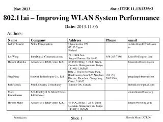
802.11ai simulations Authors: • Date:2012-03-05 Jarkko Kneckt, Nokia
Abstract • The presentation provides simulation results for active and passive scanning. • The statistics of scanning overhead and scanning quality are explained and showed. • The benefits of the 802.11ai active scanning enhancements are clearly shown. Jarkko Kneckt, Nokia
Simulation scenario 30m • A single room indoor scenario with 4 APs and 4 background traffic STAs • When background traffic was used, each background STAs transmitted and received 2Mbps data (4Mbps per STA) • 802.11ac 40MHz, 2*2 MIMO • The TGac propagation model was used 10m 10m 10m AP AP STA STA 10m 30m STA STA AP 3m AP 3m 10m Jarkko Kneckt, Nokia
Simulation scenario • 10000 STAs were created to random positions within the room at random intervals • The STAs were created with mean of 1 ms, 10 ms and 100 ms intervals • This results to 3 different real time simulation lengths (10s, 100s and 1000s) • Following steps were taken for all the created STAs: • Performed scanning to discover AP with the best RxP level • Passive scanning STA listens to the channel for 100 ms • Active scanning STA listens to the channel for 10 ms after it has transmitted a Probe Request • After the scanning the STA transmits and receives a frame (200 octets) with one (the selected) AP • The STA is removed from the simulation Jarkko Kneckt, Nokia
Simulation scenario • The management frames used AC 3, background data AC1 • Default EDCA parameters were used • Beacon, Probe Request and Probe Response were transmitted at lowest MCS at 20 MHz transmission bandwidth (6 Mbit/s) • Beacon frame is 145 octets, TX ON 220 micro seconds • Probe Request is 101 octets, TX ON 156 micro saeconds • Probe Response is 165 octets, TX ON 240 microseconds • Additional information for one BSS increases frame size by 15 octets • Probe Delay is 6 ms Jarkko Kneckt, Nokia
Simulated scanning mechanisms • The simulations benchmarked 4 different scanning mechanisms: • Passive scanning • Active scanning • Active scanning with enhancement set 1 • Active scanning with enhancement set 1 and 2 • The scanning mechanisms are described in more details in the following slides Jarkko Kneckt, Nokia
1. Passive scannning • Beacons are transmitted on every 100 TU from each AP • Each AP selects random time to transmit the first Beacon, i.e. the Beacon transmission times between APs is not coordinated • The scanning STA listens to the channel for 100 TUand then selects the strongest AP from which it has received a beacon Jarkko Kneckt, Nokia
2. Active scanning • When a STA is created, it starts Probe Delay (6tu) timer and listens to the channel • If a PHYRxStart.indication primitive is received or Probe Delay is elapsed, the STA transmits a Probe Request to broadcast address • All the APs that received the request will transmit Probe Response to the broadcast address • All STAs receive all beacons and probe responses to get information of all APs • When 10 ms has elapsed since the probe request is sent, the strongest known AP is selected • Please note that active scanning takes less than 20 ms Jarkko Kneckt, Nokia
Jarkko Kneckt, Nokia Active scanning example Please note that in all active scanning modes only one probe request was transmitted per a scanning STA
3. Active scanning with enhancement set 1 • This active scanning has enhancements to cancel the transmission of Probe Response: • The Probe Response transmission is cancelled, if TBTT is within the next 5tu, i.e. Beacon replaces the Probe Response • AP will respond to multiple similar Probe Requests with a single Probe Response • If terminal receives a Beacon or Probe Response during probe delay it will put the AP to filter list of the probe request • The APs in filter list shall not respond to the Probe Request Jarkko Kneckt, Nokia
4. Active scanning with enhancement set 1&2 • This scanning mechanism is able to cancel the Probe Response transmission as described in the previous slide AND: • When AP receives a probe request, it will reply with a probe response containing operation parameters of all 4 APs • When AP receives a Probe Response frame including its parameters, the AP cancels Probe Response transmission Jarkko Kneckt, Nokia
Simulation results • The number of transmitted Probe Responses indicates the amount of overhead created by the scanning mechanism • The time needed to receive the operating parameters of the first and the last AP • The operating parameters include SSID, BSSID, capability, etc. • The number of operating parameters received within the scanning time • The number of APs from which a frame is received within the scanning time • The reception of frame enables the radio link assessment Jarkko Kneckt, Nokia
Jarkko Kneckt, Nokia Number of transmitted Probe Responses Without background load With background load Total number of transmitted Probe Responses Total number of transmitted Probe Responses Please note that active scanning enhancements reduce the number of transmitted Probe Response frames
Time needed to receive operating parameters of the AP • The time to receive AP operating parameters indicates the time from the creation of the STA to the first time the AP has received operating parameters of the AP • The operating parameters are SSID, BSSID, capabilities, etc. • The slide#9 shows the timing diagram of the active scanning • The operating parameters are transmitted in Beacon and Probe Response frames • Simulations of active scanning with enhancement set 2, the probe responses may contain parameters of many Aps • As described in slides 7 and 8, the simulations used constant durations to receive at channel • These durations define the duration of scanning operation Jarkko Kneckt, Nokia
Time needed to receive operating parameterswithout background load Time needed to receive the first operation parameters Time needed to receive the last operation parameters CDF, 1 = all scanning STAs CDF, 1 = all scanning STAs ms ms The passive scanning requires longer time than the active scanning. The Probe Delay (6 ms) is visible in the active scanning. Jarkko Kneckt, Nokia
Time to receive AP operating parameterswith background load Time needed to receive the first operation parameters Time needed to receive the last operation parameters CDF, 1 = all scanning STAs CDF, 1 = all scanning STAs ms ms The passive scanning results are similar regardless of background traffic. The probe delay is no longer visible in active scanning. Jarkko Kneckt, Nokia
Number of APs which operating parameters are received • The operating parameters transmission may have failed for many reasons: • The probe request, probe response and beacon frame are transmitted only once • With background traffic collisions in TXOP obtaining may occur • The Scanning STAs may have received probe responses that were transmitted as a response to probe request transmitted by other STA • When STA creation interval was 100 ms, retransmission logic for probe request and use of acknowledgements should increase the number of received operating parameters Jarkko Kneckt, Nokia
Number of APs from which the operating parameters are received Without background load With background load Amount of scanning STAs Amount of scanning STAs Total number of APs which parameters are received Total number of APs which parameters are received The active scanning with enhancement sets 1&2 and passive scanning receive operating parameters. Perhaps the colliding probe responses are visible at other active scanning results. Jarkko Kneckt, Nokia
Number of APs from which a frame is received • The number of APs from which a frame is received indicates the number of APs from which the STA has received a data, ack, probe response or beacon frame • If the value is smaller than four, the scanning STA has not received a frame from all Aps • The scanning STA transmits the probe request once • No additional operation to receive a frame or scanning information from all APs was present • Additional operations make the scanning results very difficult to understand Jarkko Kneckt, Nokia
Number of APs from which a frame is received Without background load With background load Amount of scanning STAs Amount of scanning STAs Total number of APs from which a frame is received Total number of APs from which a frame is received Active scanning with enhancement sets 1&2 does not receive a frame from all APs. With background traffic all scanning mechanisms perform nicely. Jarkko Kneckt, Nokia
Conclusions • The active scanning and passive scanning have different delay • Measurement Pilot transmissions may reduce delays in passive scanning, but it is not sure will all BSSs transmit Measurement Pilots • The active scanning enhancements reduce the amount of transmitted probe responses • Without background logic, the scanning STA may need additional logic to receive a frame and assess the radio link • More advanced (re)transmission logic for probe requests and probe responses could have improved the results Jarkko Kneckt, Nokia