Download

1 / 43
600 likes | 1.32k Views
Team Members: Kyle Bloomer Josh Geiman Lucas Bennett. Potentiostat. Team Sponsor: Dr. Cindy Harnett Team Mentor: Dr. Andy Dozier. Harnett Lab. Dr. Harnett's laboratory needs 15 potentiostats for her microfluidics lab

E N D
Team Members: Kyle Bloomer Josh Geiman Lucas Bennett Potentiostat Team Sponsor: • Dr. Cindy Harnett Team Mentor: • Dr. Andy Dozier
Harnett Lab • Dr. Harnett's laboratory needs 15 potentiostats for her microfluidics lab • Off the shelf potentiostats range in price from $5K to $10K, which is prohibitive for an instructional lab Commercial Potentiostat
What is a Potentiostat? • A Potentiostat is the electronic hardware required to control a three electrode cell and run most electro-analytical experiments. • An electronic instrument that controls the voltage difference between a Working Electrode and a Reference Electrode. • It measures the current flow between the Working and Counter Electrodes.
History - Ardustat • A previous potentiostat was attempted by a project team using an open source design, the Ardustat • Hardware used was an Arduino processor board, with a prototype “daughter board” • The Ardustat was a two electrode configuration • Ardustat electrical design was poorly documented, which caused the project team to have difficulty implementing it for the project • Software design had no documentation or comments for either the firmware or the application software • The team was unable to meet the project goals
Ardustat Code Example Before Ben After Ben
Research • We have found an open source, three electrode potentiostat, known as the “Cheapstat” • Cheapstat was developed by UC Santa Barbara to provide an affordable alternative to COTS potentiostats
Cheapstat Features • Input parameters must be set through an onboard LCD and 5-way joystick • The display is very limited • LCD on the Cheapstat processor “box” • Provides multiple measurement modes • Square Wave • Linear Sweep • Stripping • Cyclic Voltammetry
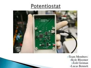
Cheapstat Hardware Front Panel PCB Assembly Joystick To Cell Electrodes
Two Different Potentiostat Systems • Two Electrode Potentiostat (Formally known as the “Ardustat”) • Three Electrode Potentiostat (Formally known as the “Cheapstat”) • Our project will entail the completion of both systems and comparison of test results of both systems.
Project Goals - Other • Characterize electrical performance for a typical electrochemical device • Compare electrical measurements betweenthe two systems • Two electrode vs. three electrode measurement differences • Document all materials
Design Goals - Hardware • Design and implement a three electrode potentiostat, based on the Cheapstat • Three electrode design • Ease of assembly and use by students, faculty, and staff • PCB assembly techniques • USB processor to PC interface • External power sources • Full documentation of hardware • Schematics • Simulation results • Assembly diagrams • List of Materials
Major Components • Processor • Firmware • Display/Data Management System (DDMS) • Voltage Converter
Processor Requirements • Capture the test configuration • Measurements to be made, ranges, etc. • Execute the test using the measurements that have been established by the operator • Log and time stamp test results in NVRAM • Send measurement data to Display/Data Management System (DDMS) during test • When polled by the DDMS, send the test results in CSV format to a file on the PC
DDMS Requirements • Test Mode • Execute test script that was entered during Pre-Test • Display results during test • Post Processing • Report generation
Voltage Converter • Three options are available: • Wall Wart • USB • Battery power • Microprocessor requires 5 VDC • Estimated 3 watts
Design Goals - Software • Develop GUI and firmware using modern software engineering techniques • No spaghetti code • Comment all code • Provide a software library • Document all the application software and firmware • Installation notes • User’s Manual
Major Components • Display/Data Management System (DDMS) • Ardustat • Arduino Development Board • Daughtercard
DDMS Requirements • Capture Input Parameters • Transmit Configuration to Arduino Development Board • Start Experiment Procedure • Export Logged Data
Arduino Development Board • Capture Configuration • Send Commands to Daughtercard • Export Measured Data
Daughtercard • Capture Measurements • Send Measurements to Arduino Development Board
Experiment • Prepare four orange juice samples, one as a control, the other three containing the addition of exogenous ascorbic acid at 0.1,.02, and 0.3M respectively. • Prepare a working electrode using a graphite pencil “lead”. • Prepare a reference electrode using a standard Ag/AgCl electrode. • Prepare a counter electrode using a piece of platinum wiring. (This will not be used for the Two Electrode Potentiostat configuration)
Experiment • Attach the electrodes to the Potentiostat systems. • Perform a cyclic voltammetry test taken from 200 to 900 mV, with a constant current of 550 mV. • Export the data to CSV file and graph the results. • Analyze graphed results against Rowe’s results using an eye inspection test.
Results • Two Electrode Potentiostat
Results • Three Electrode Potentiostat
Conclusions • Although the tests show that both systems work, the results were not as expected • Several possibilities: • Ag/AgCl reference electrode • Relay usage • Firmware implementation(?) • Chemical procedure integrity
Future Work • Universal System • Verify suggested conclusion and recommendations • Two Electrode Potentiostat • Other modes of operation • Calibration settings • Three Electrode Potentiostat • Implement DDMS GUI • Removed joystick and LCD