Download

1 / 40
430 likes | 605 Views
ENGINEERING GRAPHICS 1E9. Lecture 5: Perspective. Perspective/Central projection. Perspective is a geometric method of representing on paper the way that objects appear in real life i.e. they get smaller and closer together the further away they are from the eye of an observer.

E N D
ENGINEERING GRAPHICS1E9 Lecture 5: Perspective
Perspective/Central projection • Perspective is a geometric method of representing on paper the way that objects appear in real life i.e. they get smaller and closer together the further away they are from the eye of an observer. • It is the most realistic of all pictorial drawings • It is is the way real three-dimensional objects are pictured in a photograph that has a two-dimensional plane • Perspective or central projection is used in creative art or technical sketching but seldom in technical drawing
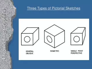
Pictorial drawings Perspective drawings differ from other types of pictorial drawings. In Isometric, Dimetric, and Trimetric drawings, the lines remain parallel and never converge at a single point. They are useful for conveying technical information but lack the quality of realism when compared to the perspective view.
Perspective System MAIN ELEMENTS • The observer’s eye • The object • The plane of projection • Line of sight
Perspective System • Observer’s eye is station point SP and the visual rays are the line of sights • Picture plane is the plane of projection or the paper • Visual ray at eye level marks horizon on picture plane
Vanishing Point • The lines parallel to each other but not parallel to the picture plane converge towards a single point on the horizon - VANISHING POINT
Notes • Observer’s eye is station point SP • Visual ray at eye level marks horizon on picture plane. The horizon line (HL) is the position of horizon. • The central line of sight should direct towards the centre of interest. • The location of the picture plane (PP) determines the size of the object on the PP. Moving the PP alters perspective or scale but not proportion. • The lines parallel to each other but not parallel to the PP (horizontal lines) converge towards a single point on the horizon - Vanishing points (VP) • The ground line (GL) represents the edge of ground plane on which object rests. GL defines the lower limit of drawing.
Types of Perspective • 1-point perspective/Parallel perspective • 2-point perspective/Angular perspective • 3-point perspective
One-point Perspective • One face of object is parallel to picture plane, one VP
Two-point Perspective • Object at angle with picture plane, but vertical edges are parallel to picture plane, two VP
Three-point Perspective • No system of parallel edges with picture plane, three VP
1-point perspective drawing (1) A simple one-point perspective of a cube is to be constructed from a plan view Step 1Establish an arbitrary horizon line (HL) depending on the eye level you wish to portray Step 2 Locate the picture plane (PP) so that it does not interfere with the drawing. (The PP may be same as HL)
1-point perspective drawing(2) Step 3 Draw the plan view above or below the PP (easier to draw it resting on top of PP)
1-point perspective drawing(3) Step 4Draw the ground line (GL) in an arbitrary location below and parallel to the PP
1-point perspective drawing(4) Step 5Locate the station point (SP) not less than twice the width of the object and directly in front of or to one side of the plan view. (SP may also be placed 2 or 3 times the object’s greatest length from the nearest point of the plan view but if placed any closer, distortion of the perspective will result.)
1-point perspective drawing(5) Step 6 Project the width of the plan view to the GL. Step 7Draw the elevation of the object on GL. If the plan view of the object is touching the PP, the elevation is true in size. If the plan view is behind or in front of PP, the elevation is smaller or larger, respectively Step 8 Project a vertical line from the SP to the HL to locate the VP
1-point perspective drawing(6) Step 9From the corners of the front view (D, E, G and F), draw visual rays to VP
1-point perspective drawing(7) Step 10 The line from point A of the plan view to SP intersects the PP at point H. Draw a perpendicular line from H to intersect the visual rays (points J and K).
2-Point perspective drawing we are going to create a 2 Point Perspective view drawing of our subject working from plan and elevation view STEP 1
2-Point perspective drawing STEP 2 The first line to draw will be the Picture Plane
2-Point perspective drawing STEP 3 Place the lower right corner of Plan View on the PP and rotate it clockwise. The choice of 30° is arbitrary, but should provide a good view
2-Point perspective drawing STEP 4 In Fig. 4 we will locate the Station Point. Measure the horizontal width of our Plan View (X) and double it. Extend a vertical line from the corner that touches the Picture Plane downward. At two times X we will locate the Station Point.
2-Point perspective drawing STEP 5 Draw lines for the Horizon and Ground Line Fig. 5. The location of these lines are infinitely variable.
2-Point perspective drawing STEP 6 Draw 2 lines from the SP that are parallel to the bottom edges of the Plan View Fig 6. The lines should intersect with the PP (points a & b). Next draw vertical lines from points a & b to the HL. The point where these vertical lines intersect the HL is where the left and right vanishing points (VPL & VPR) will be located.
2-Point perspective drawing STEP 7 The last part of preliminary layout will be to place the Side Elevation view from Fig. 1 onto the GL. Project a line (orange dashed line b) from the top of the Elevation View to the vertical Line Of Sight (LS) Fig. 7.
2-Point perspective drawing STEP 8 We are now ready to start projecting lines to the vanishing points. Referring to Fig. 8, draw lines from both vanishing points (VPL & VPR) to the top and bottom reference points of our subject (points a & b).
2-Point perspective drawing STEP 9 To locate the vertical lines on our subject, draw lines from the SP to corners a & b on the Plan View Fig. 9. At the point where these lines intersect the PP, draw vertical lines (orange dashed lines) downward to intersect the vanishing point projection lines.
2-Point perspective drawing STEP 10 Using the same procedure as shown in Fig. 9, find the smaller features on the subject in both the Plan View and the Elevation View (a & c) in Fig. 10.
2-Point perspective drawing STEP 11 Project the smaller features on the subject in both the Plan View towards the vanishing point projection lines Fig. 11.
2-Point perspective drawing STEP 12 The last step is to darken the object's construction lines, and heavy in the visible final edge lines, to increase readability Fig. 12.