Download
1 / 10
480 likes | 1.7k Views
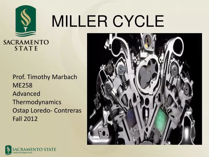
MILLER CYCLE. Prof. Timothy Marbach ME258 Advanced Thermodynamics Ostap Loredo- Contreras Fall 2012. Miller Cycle Background. The Miller cycle was patented by Ralph Miller , an American engineer, US patent 2817322 dated Dec 24, 1957.

E N D
MILLER CYCLE Prof. Timothy Marbach ME258 Advanced Thermodynamics Ostap Loredo- Contreras Fall 2012
Miller Cycle Background • The Miller cycle was patented by Ralph Miller, an American engineer, US patent 2817322 dated Dec 24, 1957. • The engine may be two stroke or four stroke and may be run on diesel fuel, gas fuel or dual fuel. • Mazda is the only known manufacturer that successfully produced a Miller cycle engine from 1995-2002 on a Mazda Millenia 2.3lts V6, and currently in Japan 1.3 lts Mazda 2. • Other Manufactures such as Subaru are nowadays working on prototype engines(Subaru B5-THP).
Miller Cycle Highlights • Intake valves closing is delayed and part of the air goes back into the intake manifold. • Expansion ratio is increased without increasing compression ratio by changing the shape of the piston. • Excellent output power and specific power. • Thermal Efficiency improves without risk of knocking, and pumping losses. • Actual compression stroke occurs in the latter 70% to 80% of the compression stroke • NOx reduction.
Miller Cycle 0–1 is an isobaric process. 1–1 Intake blowback. 1a–2a is an isentropic compression process. 2a–3a is an isochoric heating process. 2a–3a-4a combustion and expansion process. 3a-4a Isentropic expansion. 4a-1 Constant volume heat rejection 1-0 Constant pressure exhaust process
Miller Cycle 20 mpg-US (12 L/100 km; 24 mpg-imp)/28 mpg-US (8.4 L/100 km; 34 mpg-imp)/23 mpg-US (10 L/100 km; 28 mpg-imp)
REFERENCES 1.-Dante Giacossa Endothermic Engines (Motori Endotermici), Imprenta Juvenil,S.A. –Maracaibo,11 -08030 Barcelona, Espaňa. 2.- http://www.mazda.com/mazdaspirit/env/engine/miller.html 3.- Hatamura, K. and Hayakawa, M.: A study of the improvement effect of Miller-cycle on mean effective pressure limit for high-pressure supercharged gasoline engines, JSAE Review 18, 1997. 4.-Sieber. H, Weisser U. Holrler H, and Boulouchos, K; resduction NOX emissions of DI Diesel Engine by Application of the Miller-System: An Experimental and Numkericla Investigation. SAE paper No.960844, SAE Special publications, 1996 p.1238-1248.5.-Fukuzawa Y..Shimoda H, Kahuhama Y., Endo, H, and Tabaka, K, Development of high Efficiency Miller Cycle Gas Engine, Mitsubishi Heavy Industries, Ltd. Technical Review Vol. 38 No3(Oct. 2001). P146-150 6.- Anderson. M. Assanis D. and Filipi Z., First and Second Alw Analysis of a Naturally-Aspirated, Miller Cycle, SI engine with late intake Valve Closure, SAE Technical Paper Series 980889, International Congress and Expositions Detroit Michigan February 23-26,1998, p.1-16.