Download
1 / 36
380 likes | 814 Views
Development of a Halbach Array Magnetic Levitation System. By: Dirk DeDecker Jesse VanIseghem Advised by: Mr. Steven Gutschlag Dr. Winfred Anakwa . Outline. Introduction Previous Work Project Summary Changes to Original Proposal Physics of Halbach Array Magnets

E N D
Development of a Halbach Array Magnetic Levitation System By: Dirk DeDecker Jesse VanIseghem Advised by: Mr. Steven Gutschlag Dr. Winfred Anakwa
Outline • Introduction • Previous Work • Project Summary • Changes to Original Proposal • Physics of Halbach Array Magnets • Preliminary Calculations and Simulations
Outline Cont. • Equipment List • Lab work • Problems and Solutions • Results • Future Projects • Patents • References • Acknowledgements
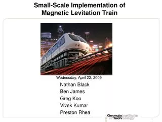
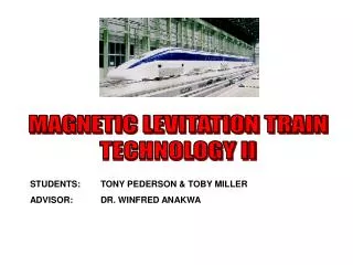
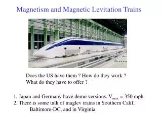
Introduction • Magnetic levitation technology can be used in high speed train applications • Maglev suspension allows trains to accelerate to over 300 mph and reduces maintenance by almost eliminating all moving parts
Previous Work • Dr. Sam Gurol and Dr. Richard Post have worked on “The General Atomics Low Speed Urban Maglev Technology Development Program” utilizing the rotary track method
Previous Work Cont. • Work by Paul Friend in 2004 • Levitation Equations • Matlab GUI • Work by Glenn Zomchek in 2007 • Design of system using Inductrack method • Successful levitation to .45 mm.
Previous Work - Results • Inductrack results from Glenn Zomchek’s project (2007)
Project Summary • The goals of our project are: • Develop an improved Halbach array magnetic levitation system to achieve 0.5 cm at a track speed of 10 m/s • Demonstrate successful levitation
Changes to Original Proposal • Focused on demonstration of levitation of the magnet device • Changed closed loop system to open loop
Physics of Halbach Array Magnets • Designed by Klaus Halbach • Creates a strong, enhanced magnetic field on one side, while almost cancelling the field on the opposite side • Peak strength of the array: B0=Br(1-e-kd)sin(π/M)/(π /M) Tesla k = 2π/λ, M = # of magnets, Br = magnet strength, d = thickness of each magnet λ = Halbach array wavelength
Physics of the Inductrack • Halbach array moving at velocity v m/sec over inductrack generates flux φ0sin(ωt), φ0 Tesla-m2, linking the circuit ω = (2π/λ)v rad/sec • Voltage induced in inductrack circuit: V(t) = ω φ0cos(ωt) • Inductrack R-L circuit current equation: V(t) = L*di(t)/dt + R*i(t)
Physics of the Inductrack Cont • Close-packed conductors, made utilizing thin aluminum or copper sheets • Allows for levitation at low speeds • Can be modeled as an RL circuit • Transfer function has pole at -R/L
Physics of the Inductrack Cont. • Dr. Post used the induced current and magnetic field to derive • Lift force: • <Fy> = Bo2w2/2kL*1/1+(R/ωL)2*e-ky1 • Drag force: • <Fx> = Bo2w2/2kL* (R/ωL) /1+(R/ωL)2*e-ky1 Where y1 is the levitation height in meters
Physics of the Inductrack Cont. • Phase shift relates to drag and levitation forces • Lift/Drag = ω*L/R • L = μ0 w/(2kdc) , where dc is the center to center spacing of conducting strips and w is the track width
Physics of the Maglev System • Force needed to levitate: F = m*9.81 Newtons m=.465 kg F = 4.56 N • Breakpoint velocity: • By solving Lift/Drag for v, vb=λω/(2π) m/sec
Equipment List • 9” radius polyethylene wheel, with a width of 2” • 57”x2”x1/4” copper sheet of thin conducting strips • 125 - 6mm cube neodymium magnets • Balsa wood structure to house the 5x25 Halbach array • Metal and hardware for motor stand • Dayton permanent magnet DC motor • Digital Force Gauge Model: 475040 • Displacement Transducer Model: MLT002N3000B5C
Lab Work - Design • Designed wheel and copper track to be built • Wheel and track were machined by Tri-City Machining
Lab Work - Design Cont. • Decided to switch from aluminum track to copper • Lower resistivity of copper(Cu = 1.68x10⁻⁸Ω*m, Al = 2.82x10⁻⁸Ω*m) • R = PcRc/(Nt*c*Ns) , where Rc is the resistivity • Lift/Drag – 2*π*v/λ*(L/R) • Aluminum Lift/Drag ratio = 0.102 • Copper Lift/Drag ratio = 0.171
Lab Work – Halbach Array Device • Balsa wood structure built • Magnets glued into balsa wood • Used shrink wrap and epoxy • Aluminum covering built to ensure magnets do not eject from balsa wood
Lab Work – Halbach Array Device Fv = Fi*cos(Θ) • Array is 5x25 magnets • λ = 28 mm • Makes our arc length approximately 8”, with an angle of 25 degrees to either side • cos(25) = .9063 • Arc length s = 9*0.436 = 3.93 • This arc length keeps 90% of the force in the vertical direction Fi Θ Force Diagram
Lab Work – Set up • Motor stand designed and built to hold motor, wheel, and balsa wood device • Holes drilled in copper track and track connected to wheel • All pieces assembled into the complete system
Lab Work – Displacement Sensor • Displacement sensor outputs linear voltage change for changes in displacement
Problems and Solutions • Copper track too short • Once holes drilled in copper, track became weak • Magnets were very difficult to glue in direction they had to be
Results • Successful levitation of 0.365 cm at 843 RPM, corresponding to a tangential velocity of 10.0 m/s • Materials for shield are ordered and will be built
Future Projects • Closed-loop control of levitation height • Dynamically balance wheel • More dampening of vibration
Acknowledgements • Dr. Winfred Anakwa • Mr. Steven Gutschlag • Mr. Joe Richey and Tri-City Machining • Mr. Darren DeDecker and Caterpillar Inc. • Mrs. Sue DeDecker • Mr. Dave Miller
Richard F. Post Magnetic Levitation System for Moving Objects U.S. Patent 5,722,326 March 3, 1998 Richard F. Post Inductrack Magnet Configuration U.S. Patent 6,633,217 B2 October 14, 2003 Richard F. Post Inductrack Configuration U.S. Patent 629,503 B2 October 7, 2003 Richard F. Post Laminated Track Design for Inductrack Maglev System U.S. Patent Pending US 2003/0112105 A1 June 19, 2003 Coffey; Howard T. Propulsion and stabilization for magnetically levitated vehicles U.S. Patent 5,222,436 June 29, 2003 Coffey; Howard T. Magnetic Levitation configuration incorporating levitation, guidance and linear synchronous motor U.S. Patent 5,253,592 October 19, 1993 Levi;Enrico; Zabar;Zivan Air cored, linear induction motor for magnetically levitated systems U.S. Patent 5,270,593 November 10, 1992 Lamb; Karl J. ; Merrill; Toby ; Gossage; Scott D. ; Sparks; Michael T. ;Barrett; Michael S. U.S. Patent 6,510,799 January 28, 2003 Applicable Patents
Works Consulted • Glenn Zomchek. Senior Project. “Redesign of a Rotary Inductrack for Magnetic Levitation Train Demonstration.” Final Report, 2007. • Paul Friend. Senior Project. Magnetic Levitation Technology 1. Final Report, 2004. • Gurol, Sam. E-mail (Private Conversation) • Post, Richard F., Ryutov, Dmitri D., “The Inductrack Approach to Magnetic Levitation,” Lawrence Livermore National Laboratory. • Post, Richard F., Ryutov, Dmitri D., “The Inductrack: A Simpler Approach to Magnetic Levitaiton,” Lawrence Livermore National Laboratory. • Post, Richard F., Sam Gurol, and Bob Baldi. "The General Atomics Low Speed Urban Maglev Technology Development Program." Lawrence Livermore National Laboratory and General Atomics.
Results – Backup Table 1: Displacement Sensor Calibration Measurements
Results – Backup Table 2: Force Sensor Measurement
Results – Backup Table 3: Displacement Sensor Measurements