Download
1 / 58
580 likes | 738 Views
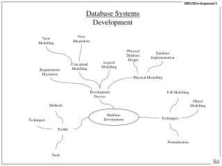
COP 4710: Database Systems Fall 2013 Chapter 3 – Logical Data Modeling And The Relational Data Model. Instructor : Dr. Mark Llewellyn markl@cs.ucf.edu HEC 236, 407-823-2790 http://www.cs.ucf.edu/courses/cop4710/fall2013. Department of Electrical Engineering and Computer Science

E N D
COP 4710: Database Systems Fall 2013 Chapter 3 – Logical Data Modeling And The Relational Data Model Instructor : Dr. Mark Llewellyn markl@cs.ucf.edu HEC 236, 407-823-2790 http://www.cs.ucf.edu/courses/cop4710/fall2013 Department of Electrical Engineering and Computer Science Computer Science Division University of Central Florida
The relational data model is based on the concept of mathematical relations. Codd (the guy who proposed the relational model) was a trained mathematician and he used terminology taken from this discipline, primarily set theory and predicate logic. The Relational Data Model
Relation: A relation is a table (matrix) with rows and columns. Relations hold information about the objects modeled in the db. Attribute: An attribute is a named column of a relation. An attribute is some characteristic of an entity (or relationship) that is modeled in the database. Attributes can appear in any order in a relation. Domain: A domain is the set of allowable values for one or more attributes. Every attribute is defined on some domain. Domains may be distinct for each attribute, or two or more attributes may be defined on the same domain. The Relational Data Model (cont.)
Tuple: A tuple is a row of a relation. Tuples can appear in any order in a relation and the relation will remain the same, and therefore convey the same meaning. Degree: The degree of a relation is the number of attributes it contains. Cardinality: The cardinality of a relation is the number of tuples it contains. Relational database: A collection of normalized relations with distinct relation names. The Relational Data Model (cont.)
An Example Relation attributes cardinality staff relation degree
To understand the true meaning of the term relation, we need to review some basic math concepts: Given two sets D1 and D2 where D1 = {2, 4} and D2 = {1, 3, 5} The Cartesian product of these two sets, written D1 D2, is the set of all ordered pairs such that the first element is a member of D1 and the second element is a member of D2. D1 D2 = {(2, 1), (2, 3), (2, 5), (4, 1), (4, 3), (4, 5)} Any subset of this Cartesian product is a relation. Thus, we could produce relation R such that: R = {(2, 3), (4, 3)} We can specify some condition which will select elements from D1 D2 to be included in R, such as: R = {(x, y) | x D1, y D2, and y = 3} What is a Relation
Given three sets D1, D2, and D3 where D1 = {2, 4}, D2 = {1, 3}, and D3 = {3, 6} The Cartesian product of three sets, written D1 D2 D3 , is the set of all ordered triples such that the first element is a member of D1, the second element is a member of D2, and the third element is a member of D3. D1 D2 D3 = {(2, 1, 3), (2, 1, 6), (2, 3, 3), (2, 3, 6) (4, 1, 3), (4, 1, 6), (4, 3, 3), (4, 3, 6)} Any subset of this Cartesian product is a relation. In general, if D1, D2, ... Dn are n sets. Their Cartesian product is defined as: and generally written as: What is a Relation (cont.)
A relational schema is a named relation defined by a set of attribute and domain name pairs. Ri = {A1:d1, A2:d2, ..., An:dn | d1 D1, d2 D2, ..., dn Dn} A relational database schema is a set of relation schemas, each with a distinct name. R = {R1, R2, ..., Rn} What is a Relation (cont.)
A relation has the following properties: The relation has a name that is distinct from all other relation names in the relational schema. Each cell (attribute) contains exactly one atomic value. Each attribute has a distinct name. The values of an attribute are all from the same domain. Each tuple is distinct; there are no duplicate tuples. The order of the attributes has no significance. The order of the tuples has not significance, theoretically. (However, in practice, the order may affect the efficiency of accessing tuples. Much more on this later.) What is a Relation (cont.)
There is an important distinction to be made between a relation schema and a relation instance. The schema is the name and attributes for the relation and is relatively immutable. An instance is a set of tuples for that relation, and the instance may change frequently. Indeed most updates and certainly every insert and deletion will change the instance. A snapshot database models the current “state” of the real world which is captured in the database. At any given moment in time it is modeling the current “instance” of the real world. If the real world state changes, so too must the database to maintain the representation of the current real world instance. Relation Schemas vs. Relation Instances
A B A B C B C A C 2 4 3 2 2 1 1 2 3 4 1 4 4 3 1 2 2 2 1 3 2 1 4 1 1 4 2 4 2 2 1 3 1 3 1 4 3 3 1 3 1 3 1 2 1 3 1 4 a relation instance a relation instance a relation instance A B C a relation instance Equivalent Relations equivalent relation instances this relation instance is not equivalent to any of the other three
During logical design you transform the conceptual design into relational database schemas. The inputs to the process are the E-R diagrams and the outputs are the relational schemas. Mapping the E-R diagrams to relations is a relatively straightforward process with a well-defined set of rules. In fact many CASE tools (Computer Aided Software Engineering tools) can automatically perform many of the conversion steps. However, it is important that you understand the steps in this process for three reasons: CASE tools often cannot model more complex data relationships such as ternary relationships and superclass/subclass relationships. These steps will need to be done manually. There are some legitimate alternatives where you must manually chose an alternative. You need to be prepared to perform a quality check on the results obtained with the CASE tool. Logical Design
In the steps that we’ll need to follow to map E-R diagrams into relational schemas, it will be helpful to remember that we’ve defined three basic types of entities which are summarized below: Regular (strong) entities are entities that have an independent existence and generally represent real-world objects such as persons or products. Represented in ERDs by rectangles with a single line. Weak entities are entities that cannot exist except with an identifying relationship with an owner (strong) entity type. Weak entities are identified by a rectangle with a double line. Associative entities (also sometimes called gerunds) are formed from many-to-many relationships between other entity types. Associative entities are represented by a rectangle with a single line that enclosed the diamond relationship symbol. Logical Design (cont.)
Each regular entity in an ERD is transformed into a relation schema. The name given to the relation is generally the same as the entity type. Each simple attribute of the entity type becomes an attribute of the relation schema. The identifier becomes the primary key of the corresponding relation. Mapping E-R Diagrams to Relational Schemas STEP 1: Mapping Regular (Strong) Entities
STEP 1: Map Regular (Strong) Entities - EXAMPLE customer customer_id customer-name customer-address customer-id customer-name customer-address Customer relation Mapping E-R Diagrams to Relational Schemas (cont.) E-R diagram customer
Composite Attributes: When a regular entity type has a composite attribute, only the simple component attributes of the composite attribute are included in the new relation schema. customer customer_id customer-name customer-address (street, city, state, zip) customer-id customer-name street city state zip Customer relation Mapping E-R Diagrams to Relational Schemas (cont.) E-R diagram customer
Multi-valued Attributes: When a regular entity type contains a multi-valued attribute, two new relation schemas (rather than one) are created. The first relation schema contains all of the attributes of the entity type except the multi-valued attribute. The second relation schema contains two attributes that form the primary key of the second relation schema. The first of these attributes is the primary key of the first relation schema, which becomes a foreign key in the second relation. The second is the multi-valued attribute. The name of the second relation should capture the semantics of the multi-valued attribute. Mapping E-R Diagrams to Relational Schemas (cont.)
Multi-valued Attributes Example: employee employee-id employee-name employee-address {skill} employee employee-id employee-name employee-address Resultingrelation schemas employee-skill employee-id skill Mapping E-R Diagrams to Relational Schemas (cont.) E-R diagram Arrow represents a referential integrity constraint. In table employee-skill the attribute employee-id is a foreign key, i.e., it is a primary key in another table. The arrow links the attribute to the table where it is the primary key.
Multi-valued Attributes: Notice in the previous relational schemas constructed due to the multi-valued attribute skill, that the resulting relation schema employee-skill has only key attributes. Each tuple simply records the fact that a given employee possesses a certain skill. This provides the database designer the opportunity to suggest to the users that new attributes can be added to this relation. For example, the attributes years-experience and/or certification-date might be appropriate new values to add to this relation. Mapping E-R Diagrams to Relational Schemas (cont.)
Recall that a weak entity type does not have an independent existence, but exists only through an identifying relationship with another entity type called the owner. A weak entity does not have a complete identifier, but must have an attribute called a partial identifier that permits distinguishing the various occurrences of the weak entity for each owner entity instance. The following procedure assumes that you have already created a relation schema corresponding to the identifying entity type. If you have not done this – do it now before proceeding. Mapping E-R Diagrams to Relational Schemas STEP 2: Mapping Weak Entities
For each weak entity type, create a new relation schema and include all of the simple attributes (or simple components of composite attributes) as attributes of this relation schema. Then include the primary key of the identifying relation as a foreign key attribute in this new relation schema. The primary key of the new relation schema is the combination of this primary key of the identifying relation and the partial identifier of the weak entity type. Mapping E-R Diagrams to Relational Schemas STEP 2: Mapping Weak Entities - continued
employee employee-id employee-name Resulting relation schemas dependent first-name middle-name last-name employee-id DOB gender Mapping E-R Diagrams to Relational Schemas STEP 2: Mapping Weak Entities - EXAMPLE dependent employee PK dependent-name (first-name, middle-name,last-name) PK employee-id employee_name FK1 employee_id Dob gender E-R diagram
The procedure for mapping relationships into the relational model depends on both the degree of the relationship (unary, binary, ternary, etc.) and the cardinalities of the relationships. We’ll look at the most common and important of these over the next several pages. Note that binary 1:M and binary M:1 relationships are symmetric. Mapping E-R Diagrams to Relational Schemas STEP 3: Mapping Binary Relationships
For each binary 1:M relationship, first create a relation schema for each of the two entity types participating in the relationship using the procedure from Step 1. Next, include the primary key attribute (or attributes) of the entity on the one-side of the relationship as a foreign key in the relation that is on the many-side of the relationship. (The primary key migrates to the many-side.) Mapping E-R Diagrams to Relational Schemas STEP 3: Binary 1:M Relationships
customer customer-id customer-name customer-address Resulting relation schemas order order-id order-date customer-id Mapping E-R Diagrams to Relational Schemas STEP 3: Binary 1:M - EXAMPLE customer order customer-id customer-name customer-address order-id order-date E-R diagram
For each binary M:N relationship between two entity types A and B, first create a new relation schema C. Include as foreign key attributes in C the primary key for each of the two participating entity types A and B. These attributes becomes the primary key of relation schema C. Any non-key attributes that are associated with the M:N relationship between A and B are included in the relation schema C. Mapping E-R Diagrams to Relational Schemas STEP 3: Binary M:M Relationships
Mapping E-R Diagrams to Relational Schemas STEP 3: Binary M:N - EXAMPLE unit-price vendor raw materials E-R diagram material-id unit-of-measure standard-cost vendor-id vendor-address vendor-name raw materials material-id standard-cost unit-of-measure quote Resulting relation schemas material-id vendor-id unit-price vendor vendor-id vendor-name vendor-address
The process of mapping such a relationship onto relation schemas requires two steps. Two relations are created, one for each of the participating entity types. The primary key of one of the relations is included as a foreign key in the other relation. In a 1:1 relationship, the association in one direction is nearly always an optional one, while the association in the other direction is mandatory (recall participation constraints). You should include in the relation on the optional side of the relationship the foreign key of the entity type that has the mandatory participation in the 1:1 relationship. This approach will avoid the need to store null values in the foreign key attribute. Any attributes associated with the relationship itself are also included in the same relation as the foreign key. Mapping E-R Diagrams to Relational Schemas STEP 3: Binary 1:1 Relationships
nurse nurse-id name date-of-birth Resulting relation schemas care center center-name location nurse-in-charge date-assigned Mapping E-R Diagrams to Relational Schemas STEP 3: Binary 1:1 - EXAMPLE date-assigned nurses care center E-R diagram nurse-id name date-of-birth center-name location null value not allowed for this attribute since care center is a mandatory participant in the relationship
Mapping an associative entity to a relation schema is similar to the procedure followed for mapping a M:N relationship. Two steps are required: Create three relation schemas, one for each of the two participating entity types, and the third for the associative entity. The relation formed from the associative entity is called the associative relation. The actions in this step depend on whether or not the associative entity was assigned an identifier in the E-R diagram. Two cases exist: An identifier was not assigned. An identifier was assigned. We’ll examine each case separately. Mapping E-R Diagrams to Relational Schemas STEP 4: Mapping Associative Entities
If an identifier was not assigned, the default primary key for the associative relation consists of the two primary key attributes from the other two relations. These attributes are then foreign keys that reference the other two relations. An example of this is shown on the next page, but note the similarity of this example to that of the M:N relationship case. Mapping E-R Diagrams to Relational Schemas STEP 4: Mapping Associative Entities – No Identifier Assigned
order order-id order-date order-line Resulting relation schemas product-id order-id quantity product product-id product-desc standard-price Mapping E-R Diagrams to Relational Schemas STEP 4: Associative Entity: EXAMPLE – no identifier assigned product order E-R diagram product-id product-desc standard-price order-id order-date order-line quantity
Sometimes the data modeler will assign an identifier (called a surrogate identifier or key) to the associative entity type on the ERD. There are two basic reasons this may occur: The associative entity type has a natural identifier that is familiar to end users. The default identifier (consisting of the identifiers for each of the participating entity types) may not uniquely identify instances of the associative entity. In either case, the process for mapping the associative entity is modified as follows: Mapping E-R Diagrams to Relational Schemas STEP 4: Mapping Associative Entities – Identifier Assigned
As before, a new associative relation is created to represent the associative entity. The primary key for the associative relation is the identifier assigned on the ERD (rather than the default key as in the previous case). The primary keys for the two participating entity types are then included as foreign keys in the associative relation. An example appears on the next page. Mapping E-R Diagrams to Relational Schemas STEP 4: Mapping Associative Entities – Identifier Assigned
Mapping E-R Diagrams to Relational Schemas STEP 4: Associative Entity: EXAMPLE – identifier assigned vendor customer shipment ship-id quantity date E-R diagram vendor-id address customer-id name . . . other attributes customer customer-id name (other attributes) shipment Resulting relation schemas shipment-id customer-id vendor-id date quantity vendor vendor-id address (other attributes)
Recall that a recursive relationship is defined as a relationship between instances of a single entity type. The two most important cases of unary relationships are the 1:M and M:M cardinalities. We’ll again look at these two cases separately as they are handled somewhat differently. Mapping E-R Diagrams to Relational Schemas STEP 5: Mapping Unary (recursive) Relationships
The entity type in the unary relationship is mapped onto a relation schema using the procedure described in Step 1. Next, a foreign key attribute is added within the same relation that references the primary key values (this foreign key must have the same domain as the primary key). A recursive foreign key is a foreign key in a relation that references the primary key values of that same relation. Mapping E-R Diagrams to Relational Schemas STEP 5: Mapping Recursive Relationships – 1:M Case
employee employee-id name birthdate Mapping E-R Diagrams to Relational Schemas STEP 5: Mapping Recursive Relationships: EXAMPLE – 1:M every employee has exactly one manager, a given employee may manage many employees E-R diagram foreign key employee Resulting relation schema employee-id name birthdate manager-id
With this type of recursive relationship, two relation schemas are created: one to represent the entity type and the other an associative relation to represent the M:N relationship itself. The primary key of the associative relation consists of two attributes. These attributes (which do not necessarily have the same name) both take their values from the primary keys of the other relation. Any non-key attribute of the relationship is included in the associative relation. The example on the next page illustrates such a case representing a bill of materials relationship among items that are assembled from other items or components. Mapping E-R Diagrams to Relational Schemas STEP 5: Mapping Recursive Relationships – M:N Case
item item-num name unit-cost item item-num name unit-cost Resulting relation schema component part-num component-num quantity Mapping E-R Diagrams to Relational Schemas STEP 5: Mapping Recursive Relationships: EXAMPLE – M:N E-R diagram quantity two primary key attributes are arbitrarily named
Recall that a ternary relationship is defined as a relationship among three entity types as shown below. Mapping E-R Diagrams to Relational Schemas STEP 6: Mapping Ternary (and n-ary) Relationships vendors supply various parts to warehouses parts vendors warehouse shipping-mode unit-cost
It is strongly recommended that all ternary (or higher) relationships be converted associative entities before proceeding further. An example is shown below which converts the ERD from the previous page into one with an associative entity: Mapping E-R Diagrams to Relational Schemas STEP 6: Mapping Ternary (and n-ary) Relationships parts shipping-mode unit-cost vendors warehouse
To map an associative entity type that links three regular entity types, create a new associative relation. The default primary key of this relation consists of the three primary key attributes for the participating entity types (in some cases additional attributes are required to form a unique primary key). These attributes then act in the role of foreign keys that reference the individual primary keys of the participating entity types. Any attributes of the associative entity type become attributes in the new associative relation. Mapping E-R Diagrams to Relational Schemas STEP 6: Mapping Ternary (and n-ary) Relationships
Mapping E-R Diagrams to Relational Schemas STEP 6: Mapping Ternary (and n-ary) Relationships - EXAMPLE ERD for ternary relationship with associative entity treatment treatment-code description patient-treatment date time results physician patients physician-id physician-name patient-id patient-name
Mapping E-R Diagrams to Relational Schemas STEP 6: Mapping Ternary (and n-ary) Relationships - EXAMPLE patient patient-id patient-name physician Resulting relational schemas physician-id physician-name patient-treatment patient-id physician-id treatment-code date time results treatment treatment-code description
The relational data model does not directly support supertype/subtype relationships. Fortunately, there are various strategies that database designers can use to represent these relationships with the relational data model. We’ll examine one of the more common techniques that has been used for modeling supertype/subtype relationships. Mapping E-R Diagrams to Relational Schemas STEP 7: Mapping Supertype/Subtype Relationships
Create a separate relation schema for the supertype and for each of its subtypes. Assign to the relation schema created for the supertype the attributes that are common to all members of the supertype, including the primary keys. Assign to the relation schema for each subtype the primary key of the supertype, and only those attributes that are unique to that subtype. Assign one (or more) attributes of the supertype to function as the subtype discriminator. Mapping E-R Diagrams to Relational Schemas (cont.) STEP 7: Mapping Supertype/Subtype Relationships
Defining subtype discriminators Given a supertype/subtype relationship, consider the problem of inserting a new instance of the supertype. Into which of the subtypes (if any) should this instance be inserted? A common approach uses a subtype discriminator. A subtype discriminator is an attribute of the supertype whose values determine the target subtype or subtypes (used when subclass membership is predicate based). Two cases arise: disjoint subtypes and overlapping subtypes. Mapping E-R Diagrams to Relational Schemas (cont.) STEP 7: Mapping Supertype/Subtype Relationships