Download
1 / 1
10 likes | 155 Views
Practical Infrared Object Tracking with Wii Remotes Sage Browning, Phillip Weber, J ü rgen Schulze California Institute for Telecommunications and Information Technology University of California San Diego sbrownin@ucsd.edu , pweber@soe.ucsd.edu, jschulze@soe.ucsd.edu. Overview.

E N D
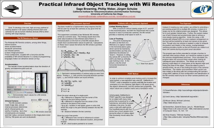
Practical Infrared Object Tracking with Wii Remotes Sage Browning, Phillip Weber, Jürgen SchulzeCalifornia Institute for Telecommunications and Information Technology University of California San Diego sbrownin@ucsd.edu, pweber@soe.ucsd.edu,jschulze@soe.ucsd.edu Overview Problems with a Trigonometric Approach Final Approach A Trigonometric Approach Limited Working Space: With a maximum vertical viewing angle of 27º, and 45º in the horizontal plane, and with the requirement that a point must be in view of at least two cameras, the Wii remote provides a relatively small space to work in. The basic model for a trigonometric setup requires that the HID be seen by at least two cameras at any given time for tracking to work. This experiment consisted of two Nintendo Wii remotes aimed at a common area. The remotes would return the pixel value locations of two infrared LED’s fixed in a horizontal plane on the front of a third Wii remote which would return accelerometer values for pitch [3]. Calculations on these return values find where the Wii remote is pointed on a screen. Goal: To develop a low cost, high accuracy method of tracking objects in 3D space utilizing infrared LED's and cameras for use as human interface devices (HID’s) when working with large displays. Instead of creating our own system, we shifted to extending a pre-existing project [5] to multiple Wii remotes, in place of a single one as the original project was designed. This allows for a much greater tracked area. Further, this system makes use of both infrared and accelerometer data to achieve a more steady tracking algorithm. Under this setup, a Wii remote with infrared LED’s in a non-coplanar arrangement on the front will be tracked by at least one camera at any given time. Though only one camera is needed in order to compute the position and rotation of the remote, overlap between cameras provides a buffer so that all IR points are visible to at least one camera during any given pose calculation. The program was further extended to include a function to calculate initial camera offsets, as it would be useless to point the cameras straightforward and level. Once calculated, the program takes into account these values when making all subsequent pose calculations. The offsets are found by placing a rigid object on a level plane at the desired origin and finding the pose of the object. Since the object’s pose is already known, we are in fact finding the pose of the cameras themselves. The rotation and translation offset vectors are then written to file along with the corresponding Wii remote’s unique MAC address so that configuration and identification of the Wii remotes need only be run when camera positions are changed. The Wii Remote as a Sensor Loss of Tracking: The point of placing two IR LED’s on the front of a Wiimote is to capture rotation in the horizontal plane (yaw), which cannot be tracked by accelerometers (as they only determine the direction of “down”). However, in rolling the remote 90º so that the IR LED’s are lined up vertically, yaw tracking is lost. In the picture, only the small horizontal movement is perceived • The Nintendo Wii Remote contains, among other things, • eleven buttons • three accelerometers • bluetooth connectivity • an infrared camera • a basic image processor • These components, coupled with a low price and the availability of Wii remote libraries in a variety of programming languages make it an attractive sensor (or toy). • Ωi = Ømax(pi/pmax - .5) • y = d/(1/tan(Ω1 + Ø1) + 1/tan(Ω2 + Ø2)) • x = y/tan(Ω1 + Ø1) - .5d • z = y/tan(Ω3 + Ø3) • Øx = tan-1((y1 - y2)/(x1 - x2)) • ∆x = ytan(Øx)∆z = ytan(Øpitch) • X’ = x + ∆x • Z’ = z + ∆z Fig 4: View from above. Accelerometers: The remote’s three accelerometers show the direction of gravity, and determine pitch and roll. Fig. 3: Geometric representation of camera setup as seen from above. Finding x1, y1 (left) and the horizontal direction pointed (right). z1 and vertical rotation are found similarly. POSIT Method In order to achieve complete pose tracking and to increase the area tracked, a new algorithm was used [4]. DeMenthon’s “POSIT” code is designed to quickly estimate the location and orientation of a non-coplanar rigid object in 3D space given the object’s dimensions, and the camera lens properties. The return values are a rotation matrix and a translation vector. References [1] DarwiinRemote <http://sourceforge.net/projects/darwiin-remote/> [2] Cwiid Library <http://abstrakraft.org/cwiid/> [3] Wiiuse Library, Michael Laforrest, <http://www.wiiuse.net/> [4] Dementhon, Daniel & Davis, Larry S., “Model-Based Object Pose in 25 Lines of Code”, 1995, International Journal of Computer Vision, 15, 123 - 131 [5] Oliver Kreylos, “Wiimote Hacking” <http://idav.ucdavis.edu/~okreylos/ResDev/Wiimote/index.html> Fig. 1: Demonstrates return values for a Wii remote in a continuous roll [1] Unfortunately, DeMenthon’s POSIT algorithm was designed for an object with many more points than is practical for a hand held device, and while his paper indicates a low error, he also uses a cube with eight points. Our handheld device with four points has a much greater error, giving the effect of a jittery object that constantly moves about the screen. • Given the pixel values pi of a single point: • Ωi= difference in degrees from the center of the camera to the point being tracked • Øi = difference in degrees from the center of the camera to the plane of the screen • (x, y, z) = location in real space, given in units of d, where the origin is the point directly between the two Wii remotes • d = distance between the two cameras • Given (x, y, z) of two points: • Øx= difference from normal in reference to screen • ∆x, ∆z = difference from absolute location, and pointed location • X’, Z’ = final location pointed to on screen Infrared Camera: The Wii remote’s camera reads image data, and an internal processor determines which infrared points are worthy of tracking. Up to four infrared points are tracked, and their radius, and pixel locations in the image plane sized 1024 by 760 pixels are sent via bluetooth. Fig. 2: Wii remote vision [2]