Download
1 / 19
190 likes | 200 Views
CMS DT Chambers. Read-Out Electronics. C. F. Bedoya, J.M. Cela, G. Dellacasa, J. Marín, V. Monaco,. J.C. Oller, P. De Remigis, A. Staiano, C. Willmott. INFN. Torino, Italy. CIEMAT. Madrid, SPAIN. “CMS DT Chambers Read-Out Electronics.” CIEMAT. Madrid, SPAIN.- INFN. Torino, Italy.

E N D
CMS DT Chambers Read-Out Electronics C. F. Bedoya, J.M. Cela, G. Dellacasa, J. Marín, V. Monaco, J.C. Oller, P. De Remigis, A. Staiano, C. Willmott INFN. Torino, Italy. CIEMAT. Madrid, SPAIN.
“CMS DT Chambers Read-Out Electronics.” CIEMAT. Madrid, SPAIN.- INFN. Torino, Italy. TWEPP-07. Prague. September 3rd – 7th 2007. 2 LHC & CMS. Compact Muon Solenoid LHC: proton-proton collider DT Chambers Endcap´s CMS is a general purpose particle detector, designed to run at the highest luminosity of LHC and optimized for muon detection and track reconstruction. • Energies up to 7 TeV per beam • Bunch crossing period of 25 ns • Luminosity 1034 cm-2 s-1 Barrel 5 wheels • 15 m length, 21.5 m diameter, 12500 Tons • Large solenoid for generate up to 4 T. • Inside the solenoid: Tracker, ECAL, HCAL • Outside the solenoid: Muon system: - Cathode Strip Chambers (CSC), - Resistive Plate Chambers (RPC´s), - Drift Tube Chambers (DT´s). Large Hadron Collider
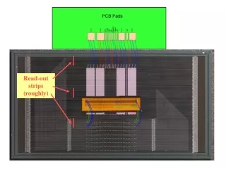
“CMS DT Chambers Read-Out Electronics.” CIEMAT. Madrid, SPAIN.- INFN. Torino, Italy. TWEPP-07. Prague. September 3rd – 7th 2007. 3 Drift Tube Chambers. Qty: 250 DT Chamber SL 1 Honeycomb SL SL 2 Anode wire Performance requirements: muon identification transverse momentum measurement: 8-15% δpt/pt at 10 GeV 20-40% δpt/pt at 1 Tev Charge assignment: correct to 99% confidence trigger with unambiguous bunch crossing identification on single and multimuon events. DT Cell GAS: Ar/CO2 (85/15) High Voltage: wires 3.6 kV strips 1.8 kV cathodes -1.2 kV Tmax < 400 ns Drift velocity ~ 55 μm/ns Resolution < 200 μm => 1 ns Efficiency ~99%
“CMS DT Chambers Read-Out Electronics.” CIEMAT. Madrid, SPAIN.- INFN. Torino, Italy. TWEPP-07. Prague. September 3rd – 7th 2007. 4 DT Read-Out Electronics. GOAL: Time digitalization related to Level 1 Accept of the DT chamber signals, and data merging for reading-out the whole detector at 100kHz L1A rate. Requirements 172,200 channels. Charged particle rate ~ 1 kHz/channel. Data processing at 100 kHz L1A rate. L1A latency ~ 3.2 µs => Need to store information from several events. Bunch crossing time (25 ns) > max drift time => overlapping triggers. Multiplexation, data merging and data reduction to read-out at max 320 MBps/wheel. TTS (Trigger Throttling System) for backpressure notification or synchronization or HW problems. • Electronics in the cavern (ROB & ROS) • Environmental radiation: • neutron fluence 1010cm-2 charged particle flux 10 cm-2 s-1 10 years integrated dose 1Gy. • Up to 0.08T magnetic fields. • 10 years limited maintenance operation.
“CMS DT Chambers Read-Out Electronics.” CIEMAT. Madrid, SPAIN.- INFN. Torino, Italy. TWEPP-07. Prague. September 3rd – 7th 2007. 5 Read-Out System. DT Muon Read-Out CMS 172200 channels Time digitalization (channel resolution 0.7 ns) 128 ch/ROB 1500 ROB 30 m copper link 240 Mbps ~16 Mbps throughput 25 ch/ROS=> 1 sector 60 ROS ~ 260 bytes muon event size/ROS 100 m optical link 800 Mbps ~80 Mbps throughput 12 ch/DDU => 1 wheel 5 DDU ~ 1.4 kBevent size/DDU S-LINK64 output 320 MB/s ~ 200 MB/s throughput
“CMS DT Chambers Read-Out Electronics.” CIEMAT. Madrid, SPAIN.- INFN. Torino, Italy. TWEPP-07. Prague. September 3rd – 7th 2007. 6 ROB: Read-Out Board. • Developed at CIEMAT, Madrid (SPAIN). • Based on the High Performance Time to Digital Converter (HPTDC) developed by CERN/MIC group. • 128 LVDS input channels • Measured Cross-talk between channels < 350 ps. • Average Occupancy : 0.3 hits/(event · HPTDC) • I,V,T on board sensor. • Overcurrent protection: • powering on cycles every 700 ms (reduces to 10% power consumption). 240 Mbps serializer. BER < 10-15 • ALTERA CPLD • Clock synchronous token ring passing scheme. • Bypass on error mechanism implemented. • The Altera CPLD manages the data_ready/get_data transmission protocol. • Triple redundancy registers implemented for SEU protection. • HPTDC • Highly programmable which provides great flexibility. • LHC clock 40,08 MHz • Low resolution mode =0.78125 ns /bin. • Measured RMS resolution 260 ps. • Manages overlapping triggers, special reject mechanism. • JTAG interface for configuration and monitoring. • Bunch and event identification. • Implemented in a radiation tolerant technology, up to levels of 30 Krad total dose
“CMS DT Chambers Read-Out Electronics.” CIEMAT. Madrid, SPAIN.- INFN. Torino, Italy. TWEPP-07. Prague. September 3rd – 7th 2007. 7 ROB.Validation tests. Irradiation tests at the Cyclotron Research Centre (UCL):5·1010 p.cm-2 of 60 MeV protons. SEU: MTBFHPTDC = 3.8 days in the whole detector MTBFALTERA = 3.4 days in the whole detector Temperature cycling: Regulators(< 5mV/30ºC). 2.5 V current variations 0.4 mA/ºC. Time shift:900ps/70ºC (14ps/ºC).Max variation~40 ps/ºC. (30% due to LVDS-TTL receptors). Lifetime test: ROB fully operational at 105ºC ambient temperature for 4 months (3100 hours). Test beams with 25 ns structured beam at CERN. Oct. 01: test beam at GIF. Including a 25 ns structured beam May. 03: One full DT chamber + Minicrate operated. Oct. 04: Two DT chambers + Minicrates operated. ROB can stand high hit rates, including noisy channels (~MHz) and this only affects 1 group of 8 channels.
“CMS DT Chambers Read-Out Electronics.” CIEMAT. Madrid, SPAIN.- INFN. Torino, Italy. TWEPP-07. Prague. September 3rd – 7th 2007. 8 Minicrate Description First Level of Read-Out and Trigger electronics is located inside the CMS wheels, in the so-called Minicrate, attached to the DT chamber. It is an aluminium structure that contains: • Read-Out electronics (RO-MC): ROB´s + ROLINK • DT Muon Trigger system: Trigger boards (TRB´s) and Server Board (SB) • MC & Chamber control: CCB (Chamber Control Board) + CCB-link RO electronics is integrated sharing with the trigger system: • LVDS to TTL translated wire chamber signals • TTC (Timing & Trigger Control) signals: 40.08MHz clock, L1Accept trigger, Event and Bunch counters reset, test pulse sequence commands. •power supplies •cooling: water cooling system due to the magnetic field. •and mechanics: up to 40 different pieces designed to ease conductive refrigeration.
“CMS DT Chambers Read-Out Electronics.” CIEMAT. Madrid, SPAIN.- INFN. Torino, Italy. TWEPP-07. Prague. September 3rd – 7th 2007. 9 ROS: Read-Out Server Board. 9U VME board developed at CIEMAT. Reads-Out 25 ROB input channels => 1 sector Main tasks • Storing of the digital input data. • Data merging in eventsat 100 kHz L1A rate. • Reduction of data overhead. • Serialization and transmission to the DDU through an optical link. • -Data quality monitoring and event synchronization. Sector Collector Crate ROS boards are located in the (SC) Sector Collector crates integrated with the Trigger Sector Collector (TSC) boards. - There are 2 SC crates per wheel. - SC crates are in the towers inside the CMS cavern: Operation under magnetic field, radiation and limited maintenance. TIM board A TIM (TTC Interface Module) board has been developed at CIEMAT to receive the TTC optical signals and distribute them through a custom backplane to the whole SC crate.
“CMS DT Chambers Read-Out Electronics.” CIEMAT. Madrid, SPAIN.- INFN. Torino, Italy. TWEPP-07. Prague. September 3rd – 7th 2007. 10 ROS Description. • VME interface. • - Board configuration. • - Status monitorization. • - Remote FPGA re-programming • Internal memory for debugging purposes. GOL (Gigabit Optical Link) ASIC developed by CERN/MIC group for data serialization. 8B/10B Ethernet at 800 Mbps. HFE4190-541 VCSEL optical transmitter at 850 nm through 100 m. Programmable laser driver current. ROSVME & ROSMEM • I, V, T sensor on board. • Overcurrent protection system. • - Average consumption ~ 3.6A. GOLROS CEROS 0 CEROS 1 ROSCTRL CEROS 2 CEROS 3 TSC channel. Trigger information from the neighbour board is read and transmitted within the read-out data flow. - Digital data is deserialized and stored in 4 kB input FIFOs. - 25 input channels grouped in blocks, managed by each CEROS FPGA. - To speed up the read-out, each block of 6 channels is processed in parallel. - Data consistency and transmission errors checked by the FPGA in each group (links timeouts, parity errors, event id misalignment, missing trailers, FIFOs full and almost full, etc). - Data overhead reduction to achieve ~ 8 kBytes per event in the whole detector: Only ROB events with valid information or error status are sent to higher levels of the read-out chain. TTC input signals(40.08 MHz clock, L1A, BC0…) Event, bunch ID and orbit information are retransmitted in each event. Monitorization of eventsynchronization is performed.
“CMS DT Chambers Read-Out Electronics.” CIEMAT. Madrid, SPAIN.- INFN. Torino, Italy. TWEPP-07. Prague. September 3rd – 7th 2007. 11 ROS Architecture. Different Operation Modes Normal mode: Event and bunch information is received from the TTC system and stored in 255 words FIFOs Events are processed in parallel in each group of 6 channels. Data is sent to a common bus following a token ring scheme for serialization and optical transmission. Spy mode: A programmable number of events/words are stored in a 512 kBytes memory and read-out through VME. Snapshots of the data flow. Does not interfere with normal operation. Straight FIFO read-out: Input FIFOs can be read directly from VME. GOL debugging mode: Data is written in the memory from VME and transmitted to the GOL. Selectable bandwidth. 588 kHz 134 kHz Estimated throughput is ~80 Mbps. (DDU through an optical link at 800 Mbps (640 Mbps effective )
“CMS DT Chambers Read-Out Electronics.” CIEMAT. Madrid, SPAIN.- INFN. Torino, Italy. TWEPP-07. Prague. September 3rd – 7th 2007. 12 ROS Validation Tests. ROS board has been extensively tested in the laboratory at CIEMAT, and also integrated with other parts of the subsystem in different set-ups: INFN Torino: integration tests of ROS + DDU. Production tests of GOLROS. INFN Bologna: test jig to validate TSC data read-out. INFN Legnaro: Integration tests with 2 DT Chambers, TSC, DDU and XDAQ SW. Irradiation tests at the Cyclotron Research Centre (UCL): 5·1010 p.cm-2 of 60 MeV protons. SEU: MTBFFIFO = 2.3 days in the whole detector MTBFEQUALIZ = 17.2 days in the whole detector MTBFDESERIALIZER = 10.6 days in the whole detector ROS prototypes (ROS-8) have been successfully operated during different test beams at CERN: May 2003: One full DT chamber + 1 ROS-8. May 2004 : Two full DT chambers + 2 ROS-8. Tests under 4 T magnetic field: Final ROS was successfully operated in the Magnet Test and Cosmic Challenge for around 170 hours. No effect under magnetic field was shown. High rate tests: Data simulating muons was injected in the ROBs and 1 sector was operated at a L1A rate of 100kHz (random, Poisson distribution). ROS can stand 1 moun per event => Around 3 times expected data rate!! ROS production has already finalized and boards are being installed in the final detector.
“CMS DT Chambers Read-Out Electronics.” CIEMAT. Madrid, SPAIN.- INFN. Torino, Italy. TWEPP-07. Prague. September 3rd – 7th 2007. 13 DDU: Detector Dependent Unit. - VME64x 9U module that collects digital data from 12 ROS boards (1 CMS wheel). - Total of 5 boards located in the service room in the CMS cavern (USC55). - Main task: send a consistent event fragment to the CMS DAQ every L1A trigger. Merge data from 12 ROS Check data synchronization Scan for error codes Keep synchronization with the rest of the DAQ chain through the TTC (Timing Trigger and Control) system. - Output data readable through VME or S-LINK 64. - Monitorization through VME plus status information embedded in the data flow. - JTAG access for boundary scan operations and FPGA re-programming.
“CMS DT Chambers Read-Out Electronics.” CIEMAT. Madrid, SPAIN.- INFN. Torino, Italy. TWEPP-07. Prague. September 3rd – 7th 2007. 14 DDU: Detector Dependent Unit. DDU Input part - 12 inputs (HFBR-5710 laser receiver + TLK1501 deserializer). -3 input FPGAs (Xilinx XCV2P40) that process 4 channels in parallel. -Data packets are converted from 16 bits to 64 bits words and stored in an internal 8K FIFO. -It performs data and transmission errors detection and consistency checks. -Status stored in another 1k FIFO.
“CMS DT Chambers Read-Out Electronics.” CIEMAT. Madrid, SPAIN.- INFN. Torino, Italy. TWEPP-07. Prague. September 3rd – 7th 2007. 15 DDU: Detector Dependent Unit. Main FPGA The Main FPGA keeps synchronization with the whole CMS system. TTC signals are received through an optical link, decoded in the TTCrx ASIC and sent to the Main FPGA. In order to provide a fast feedback to the Central Trigger System, the Main FPGA is responsible of sending its status to the TTS (Trigger Throttling System): - Slow down L1A rate, - report synchronization or hardware problems in the whole DT Read-Out electronics. Reads data stored in the input FIFOs through a 64-bit bus working at 40 MHz. Builds event fragments to be sent to the DAQ. Output data is sent to an external FIFO (64k x 72-bit) readable: - via S-LINK64 (320 MB/s) - or through VME Internal Spy FIFO and random data generator for debugging purposes.
“CMS DT Chambers Read-Out Electronics.” CIEMAT. Madrid, SPAIN.- INFN. Torino, Italy. TWEPP-07. Prague. September 3rd – 7th 2007. 16 DDU: Detector Dependent Unit. Full board functionality has been extensively checked at laboratory. - The PCB has been optimized to guarantee quality of fast signals and low jitter clock distribution. - Clock jitter is minimized in the board by using a QPLL ASIC plus low jitter differential buffers. - The deserializer clock signal (40.08 MHz) has a jitter peak-to-peak value lower than 20 ps. - A special configuration has been used in the FPGAs to validate data transmission through the 64 bit buses. - A Pseudo Random Bit Generator (64-bit LFSR) is used to produce random data patterns. - Several hours of tests show no errors in the transmission. * The DDU board has been successfully tested with other components of the DT Read-Out and the CMS central DAQ, reaching a total bandwidth of 200MBytes/s * Also, the DDU has been fully validated during the Magnet Test and Cosmic Challenge (MTCC) exercise performed at CERN during summer 2006. - The final version of the board is under production. - First units are already been used for the DT system commissioning.
“CMS DT Chambers Read-Out Electronics.” CIEMAT. Madrid, SPAIN.- INFN. Torino, Italy. TWEPP-07. Prague. September 3rd – 7th 2007. 17 Magnet Test and Cosmic Challenge. From August to November 2006 most of the CMS subdetectors were operated in the Magnet Test and Cosmic Challenge at CERN. Main goals: • Commission the magnet for the first time at its nominal value of 4 T. • Operate the whole sub-detector chain in a 20ºC slice. • Test local/global trigger and readout chains, DQM, DCS, reconstruction. • Synchronization of different sub-detectors to see common muons. The whole DT Read-Out chain was successfully operated in local and in global mode: 14 DT chambers/Minicrates. 69 ROB boards. 3 ROS boards. 1 DDU board. 170 hours data taking 200 million events collected (40 M events at B=4T) Event display of a cosmic muon with a current of 18159 A (3.8 T) in the CMS solenoid. Reconstructed muon track from the DT muon segments and extrapolation into the detector.
“CMS DT Chambers Read-Out Electronics.” CIEMAT. Madrid, SPAIN.- INFN. Torino, Italy. TWEPP-07. Prague. September 3rd – 7th 2007. 18 Summary. After several years of design and production, the complete DT Read-Out system is almost ready for operation in the CMS detector. Various prototypes of the different parts have been developed and tested in laboratory as well as in diverse tests where chambers plus electronics have been debugged and optimized. Test beams with 25 ns structured beams, operation under the CMS magnet (MTCC), radiation tests, etc. The functionality of the Read-Out electronics has been satisfactorily tested and the design has been thoroughly validated. The different parts show adequate behaviour under the environmental conditions expected during the 10 years operation of CMS in LHC. Production of the read-out electronics has taken place at CIEMAT (Madrid) and at INFN (Torino) and it has comprised: 1500 ROBs boards 250 Minicrates 60 ROS boards 10 TIM boards 5 DDU boards
“CMS DT Chambers Read-Out Electronics.” CIEMAT. Madrid, SPAIN.- INFN. Torino, Italy. TWEPP-07. Prague. September 3rd – 7th 2007. 19 Summary. • Installation and commissioning of DT chambers and Minicrates in the CMS detector has been going on for the last 2 years. • At present, ROS and DDU boards are being installed and the system is being commissioned sector by sector. • 70% of the detector has been commissioned up to now with satisfactory results. • Tests include: • cosmic runs in surface and in the cavern and • test pulse runs, where the whole electronic chain is tested, by generating pulses at Front-End level that simulate vertical tracks. • Noise runs, to evaluate the amount of noise coming from the system.