Download
1 / 18
180 likes | 301 Views
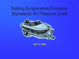
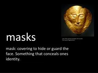
Setting Emission and Blocking masks. European Communications Office Jean-Philippe Kermoal (ECO) June 2012. Outline. Using Library. Edit Import from library Export to library. Edit. Export. Import.

E N D
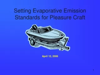
Setting Emission and Blocking masks European Communications Office Jean-Philippe Kermoal (ECO) June 2012
Using Library • Edit • Import from library • Export to library Edit Export Import Technical specifications commonly extracted from ETSI (see http://www.etsi.org/WebSite/Standards/Standard.aspx)
Editing the mask • The emission mask defaults value • Remove the default using the Clear button. • Then use the add button to add the enough blank rows for half of the emission mask. • Note the format of the data: • Offset = MHz • Unwanted = dBc • Reference bandwidth = kHz
Symmetry • Then use the Sym button to get a symetric mask
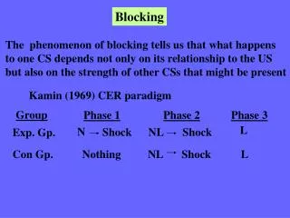
Reference/normalised bandwidth • Once SEAMCAT has generated the whole mask, first check that the values are in the correct order. • The unwanted emission diagram shows two masks The blue mask is normalised to 1MHz measurement bandwidth. The user may normalise his input to 1MHz bandwidth but it can be useful to input the mask in the bandwidth defined in the standard and allow SEAMCAT to create normalised mask. The red mask is the representation using the user defined reference bandwidth.
Store your mask on disk • Spectrum mask can be saved as .txt file • it can be reused for other workspaces using load buttons.
General System with 30 dBm in a emission bandwidth of 20 KHz Emission BW = Ref. BW = 20 KHz Ref. BW 10 KHz
Spectrum emission mask values, BS maximum output power P 43 dBm (TS25.104) CDMA FDD emission mask -BS example 3GPP TS25.104
CDMA FDD emission mask -UE example 3GPP TS25.101
Exercise #1 – edit a Mask • Assuming a BS Tx power of 43 dBm, and with addition of the ITU-R SM.329 limit above 12.5 MHz, perform the following: • Convert the dBm values into dBc • Insert the spectrum mask in SEAMCAT • Save it as .txt file • Export it as your own spectrum library 43- (-14) = 57 dBc linear 43- (-26) = 69 dBc 43- (-13) = 56 dBc 43- (-36) = 79 dBc
ACIR = f(ACLR, ACS) • ACIR = adjacent-channel interference ratio • In UL, the dominant part of ACIR is due to the UE adjacent channel leakage (ACLR) i.e. ACSBS is very large compare to ACLRUE and ACIR ≈ ACLRUE. • In DL, the dominant part of ACIR is due to the UE frequency selectivity (ACS) i.e. ACLRBS is very large compare to ACSUE and ACIR ≈ ACSUE
ACLR in SEAMCAT • No use of the ACLR directly. • Emission spectrum Mask is used
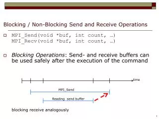
Blocking Mask (generic) Receiver Mask Rx bandwidth Blocking: • User-defined mode • Protection ratio • Sensitivity modes Rejection of the receiver fI fv Blocking Response = filtering (user defined mode) Receiver Mask Rx bandwidth Blocking: Rejection of the receiver fI fv Blocking Response = ACS (ETSI) + Blocking (ETSI) (PR and Sensitivity mode)
CDMA and OFDMA ACS • ACS is the same as the blocking attenuation input
Emission Floor • Useful when power control is used • This emission floor mask (frequency offset (MHz), emission floor (dBm), reference bandwidth (MHz)).