Download
1 / 37

E N D
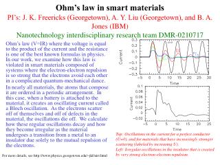
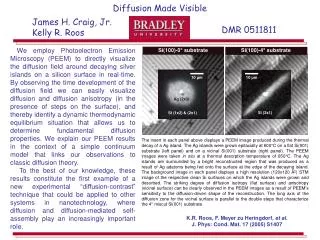
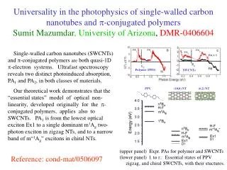
Superconductivity in Metal-mixed Ion-Implanted Polymer FilmsAdam Micolich 1, Eric Tavenner 2, Ben Powell 2, Alex Hamilton1,Matt Curry 3,Ryan Giedd 3, and Paul Meredith 2.1 School of Physics, University of New South Wales, Sydney 2052, Australia.2 Physics Department, University of Queensland, Brisbane 4072, Australia3 Center for Applied Science and Engineering, Southwest Missouri State University, Springfield MO 65804. (For more details see A.P. Micolich et al., Cond-mat 0509278).
Economics + - Ease of Production Chemical Versatility The Dream: Electronics on Plastic Replace this . . . . . . with this Replace this . . . . . . with this Flexible circuitry Replace this . . . . . . with this $10 billion $100
+ - Instead, could you use ion-implantation to modify the conductivity of plastic, just like we do with Silicon already! And so develop a cheap and simple way to create conducting plastics? An Alternative Approach You could deposit conducting polymer inks? Many conducting polymers are air/moisture-sensitive, they don't stick well, and are often quite expensive.
Ion-Implanted Plastics: Previous Studies Energetic ion beams (e.g. Ar+, Kr+) modify the near surface of insulating organic polymers to create electrical conductivity. “The room temperature resistivity of the films changes by 14 orders of magnitude from its as-deposited value of r > 1010Wcm to r 5 10-4Wcm at ion doses of 1017 cm-2” For more details see S.R. Forrest et al., Appl. Phys. Lett. 41, 708-710 (1982).
Ion-Implanted Plastics: Previous Studies Organic polymer “de-polymerises” under the ion beam, volatiles (O, H, N) are lost, and re-crosslinking creates carbon rich clusters. “XPS data of films revealed significant reduction in the heteroatoms and increased carbon content after implantation … The room temperature conductivity of these implanted polymers, typically ~80-200 S/cm, is significantly higher than that obtained to date by conventional doping techniques.” For more details see J.A. Osaheni et al., Macromol. 25, 5828-5835 (1992).
Ion Implanted Polymers What happens if we implant metal ions? All of the inert ion implanted films are strongly insulating, in an attempt to improve the conductivity a shift was made to using metallic ions as the implant species. But until recently, the best we could do is create less insulating insulators! For more details see E. Tavenner et al., Synth. Met. 145, 183-190 (2004).
However, you can instead deposit a thin layer of Sn:Sb (95:5) on the surface (as little as ~10nm) and ‘push’ this into the PEEK using a nitrogen or argon ion-beam. Ion Implanted Polymers Metal Mixed :Sb :Sb We need more metal in the surface… Implanting with metal beams can’t get enough metal into the plastic to confer metallic conductivity. There is a limiting dose because the beam starts to sputter the deposited ions away.
Experimental Methods After Sn:Sb evaporation, implantation is done using an IBM Taconic Implanter at 50kV. The samples are prepared for electrical measurements by evaporating Ti/Au contacts in the corners and using InAg solder to attach Cu wires. Samples were measured on an Oxford Instruments VTI system capable of temperatures between 200K and 1.2K, and magnetic fields up to 10T.
Superconductivity confirmed by both two terminal (left) and four terminal (right) measurements. Typical Tc ~ 1.9 – 2.7K RRR < 1.2 (ie. highly disordered metal) Superconductivity In contrast to previous samples, we see a metallic temperature dependence, and a sharp drop in resistance at T < 3K. For more details see A.P. Micolich et al., Cond-mat 0509278.
Superconductor/Polymer Composites Superconductor/polymer blends (e.g. b-ET2I3/Polycarbonate) studied previously have shown an incomplete superconducting transition and a partial Meissner effect. Laukhina et al. “At some conditions of the thermal treatment an accelerated decrease of resistivity is observed below 7K, vanishing with application of magnetic field, thus giving the first evidence of the (incomplete) superconducting transition in polymeric organic composite material.” For more details see E.E. Laukhina et al., Synth. Met. 70, 797 (1995) and A. Tracz et al., Synth. Met. 120, 849 (2001). Our material is that it is the first superconductor/polymer composite to show a zero resistance electrical state. (as far as we know)
Let’s look at some evidence to support/eliminate some of these models. Tc for bulk tin = 3.7K Bc for bulk tin = 30.5mT Bc for our material as high as 500mT! Tc for our material ~2.4K! • We can immediately eliminate bulk tin as a possible explanation, our Tc is suppressed and our Bc is enhanced compared to the bulk tin values. • This leaves only three possible models (that we know of) for the origin of superconductivity in this material. • A continuous thin film of tin (has to be thin enough to suppress Tc) (i.e., we’ve just re-invented the studies in quench-condensed systems) • A layer of granular tin mixed into a partially conducting hydrocarbon matrix • A tin-carbon molecular eutectic (unlikely) Well what’s going on? - Three possible models
Quench-Condensed Metal Studies Metals (typically Bi, Sn, Pb, etc.) are deposited by MBE onto a flat solid substrate held at 4K. Low temperature deposition under UHV conditions is essential to producing these ~10-100Å thick films and keeping them stable enough to study. For a brief review see A.M. Goldman and N. Markovic, Physics Today Nov 1998, p. 39.
Measurements repeated over a period of seven months with little change beyond a slight (< 10%) increase in the normal resistance. This is despite storage in a plastic box under ambient conditions. Metal Mixing – Does it really work that way? Cross-sectional Scanning Tunnelling Electron Microscopy (STEM) and Energy Dispersive X-ray Analysis (EDX) shows an implant mixed region that extends ~75nm into the PEEK sub-surface. This is over 7 times the thickness of the original 10nm Sn film we deposited. The implantation encapsulates the tin and thereby significantly enhances its adhesion to the plastic, which retains its native mechanical properties.
SnII-O 485.3eV Sn-Sn 484.4eV SnIV-O 486.5eV Sn-C 486.1eV Samples Photoelectron Properties 100Å Sn no implantation 200Å Sn no implantation 100Å Sn with implantation Bonding Type Peak C graphite <1% <1% 27% C aromatic C 1s 43% 35% 54% C-O, C=O 9% 3% 3% Sn-Sn 8% 14% 2% Sn 3d Sn-C <1% <1% 5% Sn-O, Sn=O 40% 48% 9% Chemical Consequences of Implantation X-ray Photoelectron Spectroscopy shows dramatic changes in the composition of the implant region. Implantation does three key things: 1: Reduce the Sn-Sn and Sn-O bonds by a factor of ~5 => breaks up the metal. 2: Increases the Sn-C bonds by a factor of ~5 => binds the tin to the plastic. 3: Massively increases the graphitic carbon content => same effect as with no metal.
Quench-Condensed Studies – Electrical Behaviour ~0.4nm ~7.5nm The quench-condensed studies of most metals (including Sn) show a thickness-controlled superconductor-insulator transition (SIT). Of particular note, as you increase the film disorder (i.e., increase the normal film resistance R0), the superconducting transition temperature should decrease towards T = 0. For a brief review see A.M. Goldman and N. Markovic, Physics Today Nov 1998, p. 39.
How does our data compare to this? We find behaviour that is very different to the QC studies – The sample with the higher normal resistance actually has the higher critical temperature Tc. Furthermore, one would naively expect that higher implant dose means more disorder and hence a higher R0, however, we observe exactly the opposite. One final key difference with the quench condensed systems…
The Antimony fraction is essential in our samples Pure Sn 95% Sn : 5% Sb If we use pure Sn, samples with thicknesses up to 40 nm are strongly insulating, whether they are implanted or not. Sb is commonly used as an impurity in Sn solders to inhibit the transition from the metallic white allotrope to the insulating grey allotrope. However, whether Sb plays any role beyond this in the post-implant structure is not yet clear.
What happens if you don’t implant? ~20nm Sn:Sb film on PEEK unimplanted In the unimplanted film, the Tc is 3.7K again, and the transition is very sharp
What happens if you don’t implant? 10nm Sn:Sb film on PEEK implanted 20nm Sn:Sb film on PEEK unimplanted The field dependence for the unimplanted films shows something quite interesting, there are ‘bumplets’ on the high-field side of the field-induced superconducting transition!
The bumplets are interesting A ‘peak effect’ is commonly observed in layered superconductors and in granular thin-films. DyBa2Cu3O7-x: Wang et al. MoSi: Okuma et al. Amorphous InOx: Paalanen et al. “An anomalous peak in the perpendicular MR has been also observed in granular films, whose origin is related to destruction of local superconductivity within each grain.” (Okuma et al.) For more details see M.A. Paalanen et al., PRL 69, 1604 (1992); T. Wang et al., PRB 47, 11619 (1993); S. Okuma et al., PRB 63, 054523 (2001) and PRB 58, 2816 (1998).
Granular Tin • We actually start out with an granular/amorphous alloy coating on the PEEK in the evaporation step, similar to that found with other materials on other substrates. Energetic Ions Smaller Granules Intimately Mixed into the Substrate • The incident energetic ions then lead to smaller granules intimately mixed into the sub-surface of the PEEK. + = So what do we think is going on?
For the higher implant dose, one could expect that it has smaller grains with a smaller inter-grain separation, and since the inter-grain hopping scales with the grain separation, this should have the lower Ro, which we see. • Furthermore, if the grains are small enough that they undergo Tc-suppression, then one could expect that the higher implant dose gives smaller grains and therefore a lower TC, which we also see. How does this sit with the electrical data?
Study a more comprehensive range of metal thicknesses to understand how pre-implant metal thickness determines the material properties. • Perform further materials characterisation studies (e.g., small-angle neutron scattering) to better establish the structural and chemical details of the implant region. • Explore whether other metals are suitable for this technique, and whether we can raise Tc with such an approach. So what next? – Short term A lot more samples and a lot more measurements. We want to:
Credits • University of NSW, Australia Dr Adam Micolich (Low T measurements) A/Prof. Alex Hamilton (Low T measurements) • University of Queensland, Australia Eric Tavenner (Fabrication, XPS/STEM) Dr Ben Powell (Superconductor Guru) Dr Paul Meredith (Project Leader/Characterisation) • Southwest Missouri State U., U.S.A. Dr Matthew Curry (Ion Implantation) Dr Ryan Giedd (Ion Implantation) • Funding • Helpful Discussions Ross McKenzie, James Brooks, Arzhang Ardavan, Stephen Blundell, Andrew Briggs, Brad Marston, Urban Lundin, Des McMorrow and Francis Pratt. • Experimental Assistance Barry Wood, Brisbane Surface Analysis Centre Centre for Microscopy and Microanalysis at the University of Queensland
Credits • University of NSW, Australia Dr Adam Micolich (Low T measurements) A/Prof. Alex Hamilton (Low T measurements) • University of Queensland, Australia Eric Tavenner (Fabrication, XPS/STEM) Dr Ben Powell (Superconductor Guru) Dr Paul Meredith (Project Leader/Characterisation) • Southwest Missouri State U., U.S.A. Dr Matthew Curry (Ion Implantation) Dr Ryan Giedd (Ion Implantation) • Funding • Helpful Discussions Ross McKenzie, James Brooks, Arzhang Ardavan, Stephen Blundell, Andrew Briggs, Brad Marston, Urban Lundin, Des McMorrow and Francis Pratt. • Experimental Assistance Barry Wood, Brisbane Surface Analysis Centre Centre for Microscopy and Microanalysis at the University of Queensland
So what next? – The future • Learn what we can really do with this system (increase Tc, minimum feature size, etc.). • Work on creating patterned versions with the view towards making devices such as Josephson Junctions and ultimately SQUIDs. • Longer term, work on achieving the missing conductivity regime (i.e., a proper semiconductor with a band-gap, etc.) – amorphous Si in PEEK? Ion Implanted Polymers Metal Mixed ?
Repeatability and Reproducibility Repeatability 001 001(2) 002 A01 A09
Hall Measurements The original plan at this point was to try and get Hall effect data for these samples in order to establish the carrier type/density and mobility of the material. For more details see V.C. Long et al., J. Appl. Phys. 80, 4202-4204 (1996). Typical range of n was ~1013 cm-2 (A08) to ~1021 cm-2 (001)
We observe critical magnetic fields Bc is as high as 500 mT. Response to a magnetic field The samples show a critical field Bc that falls linearly with increasing temperature, typical for a type II thin film superconductor. One notable feature is the noise as T approaches Tc.
Let’s look at some evidence to support/eliminate some of these models. Tc for bulk tin = 3.7K Bc for bulk tin = 30.5mT Bc for our material as high as 500mT! Tc for our material ~2.4K! • We can immediately eliminate bulk tin as a possible explanation, our Tc is suppressed and our Bc is enhanced compared to the bulk tin values. • This leaves only three possible models (that we know of) for the origin of superconductivity in this material. • A continuous thin film of tin (has to be thin enough to suppress Tc) • A layer of granular tin / partially conducting hydrocarbon • A tin-carbon molecular eutectic (unlikely) Well what’s going on? - Three possible models
The critical temperature Tc ~ 2.4K, but ranges from around 1.9K to 2.7K (in the samples so far). • The critical magnetic field Bc is as high as 500 mT. • The upper bound on the residual resistance ratio (RRR) is 1.2, indicating that our material is a highly disordered metal. • The critical current Icis of order 1 mA, with superconductivity occasionally observed at currents as high as 10 mA. • The observed metallic and superconducting behavior is repeatable after thermal cycling to room temperature, and reproducible (quantitatively similar) in nominally identical samples. • We find that the metal-mixed layer does not delaminate even after several cryogenic cycles and the implanted material shows significant durability. • We have repeated our measurements over a period of seven months with little change or degradation of the electronic properties beyond a slight (< 10%) increase in the normal resistance over this period, despite simply storing these samples in a plastic box under ambient conditions. Some key properties
Ion-implantation can be used to create cheap conducting polymers – metal mixing can produce plastic materials with metallic and superconducting properties. • These implanted plastics retain the native mechanical properties of the bulk material – they are flexible and robust. Superconductivity in the Metal-mixed Systems • While the continuous thin film is the simplest and most logical conclusion, our combined evidence (structural, chemical and electrical studies) suggests that this is not the case. • Instead, we propose that our plastic superconductor is either a mixed (tin + hydrocarbon) granular system (with very small granules potentially) or a molecular tin-carbon eutectic. Future studies will be aimed at addressing these possibilities further. Summary and Conclusion
200Å film on PEEK unimplanted 100Å film on PEEK implanted implantation + = So what does all this tell us? What this suggests is, that we start out with a granular system, the ion beam smashes up the granules and mixes them into the PEEK, giving us our superconductor/polymer composite. Granular Tin Energetic Ions Smaller Granules Intuitively this makes some sense. Also, the intimate mixing might explain why layers too thin to conduct before implantation start to conduct after implantation.
Early 1970’s: Mistake in Skirakawa’s lab leads to accidental discovery of silver looking polymer (polyacetylene) • Late 1970’s: Collaboration between Heeger, MacDiarmid and Shirakawa lead to 10 million-fold increase in conductivity of polyacetylene. • 2000: Heeger, MacDiarmid and Shirakawa win Nobel Prize in Chemistry • 2000+: First ‘organic electronics’ appear on the market as flexible displays. Conducting Polymers
Metallic and superconducting behavior is repeatable after thermal cycling, and relatively reproducible in nominally identical samples. • The metal-mixed layer does not delaminate even after several cryogenic cycles. • Measurements repeated over a period of seven months with little change beyond a slight (< 10%) increase in the normal resistance. This is despite storage in a plastic box under ambient conditions. … sure beats … The encapsulation gives some advantages