Download
1 / 62
640 likes | 876 Views
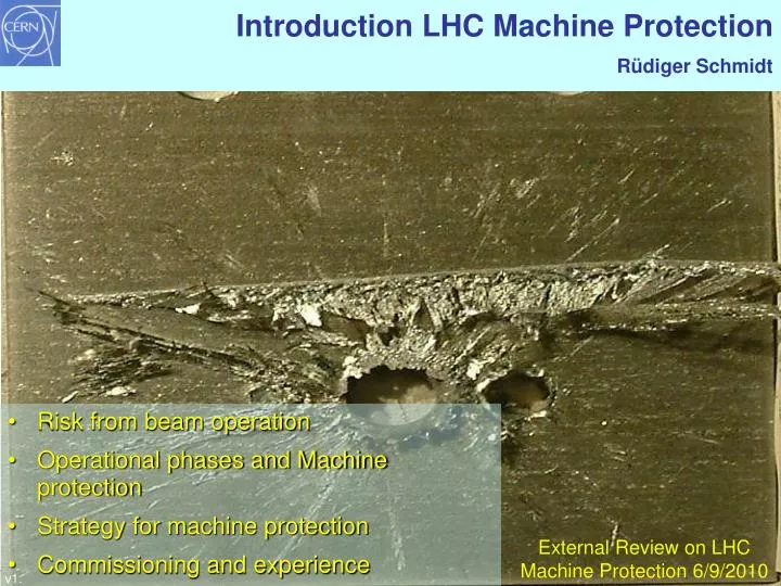
Introduction LHC Machine Protection Rüdiger Schmidt. Risk from beam operation Operational phases and Machine protection Strategy for machine protection Commissioning and experience. External Review on LHC Machine Protection 6/9/2010. v1.2. Beam damage test in SPS.

E N D
Introduction LHC Machine Protection Rüdiger Schmidt • Risk from beam operation • Operational phases and Machine protection • Strategy for machine protection • Commissioning and experience External Review on LHC Machine Protection 6/9/2010 v1.2
Accidental release of 600 MJoule stored in the LHC dipole magnets (one out of eight sectors, interconnect) during powering tests…not beam related
History and organisation • System for protection were already planned from the start of the LHC project • Beam Dumping System, Beam Loss Monitors and Collimation System • ~2000, the integration of the systems into one Machine Protection System was suggested: start of the Machine Protection WG • with the participation of experts from the main protection systems, plus operation, plus representatives from many other groups • It became clear that an interlocks system is required, to link several different systems • architecture of Beam Interlocks and Powering Interlocks was defined • MPP (Machine Protection Panel) discusses all aspects of machine protection between different teams • MPPr (MPP restricted), with experts from main protection systems and operation propose commissioning strategy and report to LMC (LHC Machine Committee)
Safety and protection for accelerators Accelerators, as all other technical systems, must respect some general principles with respect to safety • Protect the people (e.g. follows legal requirements) • Protect the environment (e.g. follows legal requirements) • Protect the equipment Machine Protection in this review: protect equipment (including the LHC experiments) from damage, activation, downtime caused by the beam– by accidental beam losses Machine Protection independent of beam (superconducting magnets, normal conducting magnets, power cables, other high power equipment, RF, etc.)
Principles for machine protection • Protect the machine • highest priority is to avoid equipment damage • second priority is to avoid quenching of magnets: with superconducting magnets it requires few mJoule to quench, beam losses in the cold part must be minimised • Protect the beam: trade-off between protection and operation • complex protection systems reduces the availability of the machine • minimise number of “false” triggers due to a failure in the protection systems (e.g. false beam dumps ) • Provide the evidence • if the protection systems stops operation (e.g. beam dumps or inhibits injection), provide clear diagnostics • if something goes wrong (near miss or even damage), it should be possible to understand the reason why • demonstrate that the Machine Protection Systems work correctly
Accidental beam losses: Risks and protection • Protection is required since there is some risk • Risk = probability of an accident (in number of accidents per year)consequences (in Euro, downtime, radiation dose to people) • Probability of accidental beam loss • What are the failure modes leading to beam loss into equipment? …there is an practical infinite number of mechanisms to lose beam • What is the probability for the most likely failures? • Consequences of accidental beam loss • Damage to equipment • Downtime of the accelerator for repair (spare parts available?) • Quench of magnets • Activation of material, might lead to downtime since access to equipment is delayed • The higher the risk, the more protection becomes important
Consequences of accidental beam loss • Accident as in sector 34 in 2008: downtime of one year • Damage to an LHC experiment: downtime of many months • Replacement of one superconducting magnet: downtime of about 2 months (warming up, cooling down) • Replacement of a collimator: downtime of a few days to maximum 2 weeks (including bake out if needed) • Replacement of another element in th warm part of LHC: downtime of a few days to maximum 2 weeks (including bake out if needed) • Quench of a magnet (or a few magnets): downtime of a few hours • Beam accidents could lead to damage of superconducting magnets, and to a release of the energy stored in the magnets (coupled systems)
Beam losses and consequences Particle losses lead to particle cascades in materials The energy deposition leads to a temperature increase Material can vaporise, melt, deform or change its mechanical properties Risk to damage sensitive equipment for beam with an energy of some 10 kJ, beam with an energy of some MJoule damages any structure (depends on beam size) Superconducting magnets could quench (beam loss into magnet with an energy of ~mJ to J) Energy deposition and temperature increase: programs such as FLUKA, MARS or GEANT are being used for the calculation of energy deposition and damage
Damage of a pencil 7 TeV proton beam copper copper, 12kJ graphite graphite, 600kJ
SPS experiment: Beam damage with 450 GeV proton beam Controlled SPS experiment • 81012 protons clear damage • beam size σx/y = 1.1mm/0.6mm above damage limit for copper stainless steel no damage • 21012 protons below damage limit for copper 25 cm 6 cm • 0.1 % of the full LHC 7 TeV beams • Three times below the energy stored in a nominal bunch train (288 bunches) injected into LHC • 48 bunches from SPS to LHC in 2010/2011 A B D C V.Kain et al
LHC: set-up and probe beam flags From the SPS damage tests and operational experience • At injection energy of 450 GeV: a loss of 1012 protons will not cause (major) damage, such as damaging the vacuum pipe • The limit decreases with energy, proportional to (E[GeV]/450)1.7, at 3.5 TeV the limit is about 31010 protons • Injection into an EMPTY machine with beam of much less intensity of 1.21010 (PROBE_BEAM_FLAG, max. possible value 1.01011) • IF no beam in LHC AND PROBE_BEAM_FLAG = FALSE: no injection • If beam intensity is below 1012 protons (injection): SETUP_BEAM_FLAG is TRUE – done in hardware • For commissioning, some of the interlocks can be masked if SETUP_BEAM_FLAG= TRUE
Probe and Setup Beam Flags at injection achieved: one injection with 4 bunches from SPS achieved: 50 bunches circulating in LHC plan for 2010/11 setup beam flag allows to mask some interlocks for tests probe beam inject beam into empty LHC
What can go wrong? Classification of failures When can it go wrong? Operational phases
Classification of failures • Type of the failure • hardware failure (power converter trip, magnet quench, AC distribution failure such as thunderstorm, valve or beam monitor in vacuum chamber, vacuum leak, RF trip, kicker magnet misfires, .…) • controls failure (wrong data, wrong magnet current function, trigger problem, timing system, feedback failure, ..) • operational failure (chromaticity / tune / orbit wrong values, …) • beam instability (due to too high beam / bunch current) • material in the beam pipe (UFO, …) • Parameters for the failure • damage potential • probability for the failure • time constant for beam loss • Be aware of combined failures risk can be derived
Time constant for beam losses Single turn (single-passage) beam loss (ns - s) • failures of kicker magnets (injection, extraction, special kicker magnets, for example for diagnostics) • transfer lines between SPS and LHC • transfer lines from LHC to beam dumping block Very fast beam loss (ms) • multi turn beam losses • due to a large number of possible failures, mostly in the magnet powering system, with a typical time constant of some 10 turns to many seconds Fast beam loss (some 10 ms to seconds) Slow beam loss (many seconds) Passive protection: relies on beam absorbers Active protection: detect and dump
LHC operational cycle and machine protection 3500 3000 2500 energy ramp ~3 MJ 20-30 MJ circulating beam coast (20-30 MJ) circulating beam Energy [GeV/c] 2000 1500 1000 beam dump ~20-30 MJ 500 0 2000 4000 -4000 -2000 time from start of injection (s) Injection: ~48 bunches from SPS per beam (481011) Nominal: 2808 bunches per beam (1.151011) and 7 TeV
Injection: Without quenching magnets or causing damage • No kick by injection kicker of circulating beam (correct synchronisation) • Injection protection absorber in place in case of kicker failure 3500 3000 2500 energy ramp ~3 MJ 20-30 MJ circulating beam coast (20-30 MJ) circulating beam Energy [GeV/c] 2000 1500 1000 beam dump ~20-30 MJ 500 0 2000 4000 -4000 -2000 time from start of injection (s) Injection: ~48 bunches from SPS per beam (481011)
Circulating beam: In case of failure, detect failure and extract beam into dump block for some failures within a few turns • No accidental firing of a kicker magnet 3500 3000 2500 energy ramp ~3 MJ 20-30 MJ circulating beam coast (20-30 MJ) circulating beam Energy [GeV/c] 2000 1500 1000 beam dump ~20-30 MJ 500 0 2000 4000 -4000 -2000 time from start of injection (s) Injection: ~48 bunches from SPS per beam (481011)
Extraction: Beams must ALWAYS be extracted into beam dump block Kicker must be synchronised with the 3 µs long beam abort gap No particles in the abort gap 3500 3000 2500 energy ramp ~3 MJ 20-30 MJ circulating beam coast (20-30 MJ) circulating beam Energy [GeV/c] 2000 1500 1000 beam dump ~20-30 MJ 500 0 2000 4000 -4000 -2000 time from start of injection (s) Injection: ~48 bunches from SPS per beam (481011)
Machine Protection during all phases of operation • The LHC is the first accelerator with the intensity of the injected beam already far above threshold for damage, protection during the injection process is mandatory • At 3.5 TeV, fast beam loss with an intensity of less than one single “nominal bunch” could damage equipment • The only component that can stand a loss of the full beam is the beam dump block - all other components would be damaged • The LHC beams must ALWAYS be extracted into the beam dump blocks • at the end of a fill • in case of failure
LHC: Strategy for machine protection Beam Cleaning System • Definition of aperture by collimators. Powering Interlocks Fast Magnet Current change Monitor • Early detection of failures for equipment acting on beams generates dump request, possibly before the beam is affected. • Active monitoring of the beams detects abnormal beam conditions and generates beam dump requests down to a single machine turn. Beam Loss Monitors Other Beam Monitors • Reliable operation of beam dumping system for dump requests or internal faults, safely extract the beams onto the external dump blocks. Beam Dumping System • Reliable transmission of beam dump requests to beam dumping system. Active signal required for operation, absence of signal is considered as beam dump request and injection inhibit. Beam Interlock System • Passive protection by beam absorbers and collimators for specific failure cases. Collimator and Beam Absorbers
Examples • Transfer and injection • Failure of normal conducting magnet and fast beam loss • Beam dump
SPS, transfer line, LHC injection and CNGS Beam is accelerated in the SPS to 450 GeV Beam with a stored energy of 0.5 MJ be transferred from SPS to LHC, at about damage limit For CNGS operation, the intensity is similar to LHC injection IR8 Injection kicker CNGS Target Switching magnet Fast extraction kicker SPS 6911 m 450 GeV / 400 GeV 0.5 MJ Acceleration cycle of 10 s Transfer line Injection kicker LHC IR2 Fast extraction kicker 1 km Transfer line
Failure of a kicker magnet Extraction kicker magnet: • wrong pulse strength • wrong timing Injection kicker magnet: • wrong pulse strength • wrong timing IR8 Injection kicker CNGS Target Switching magnet Fast extraction kicker SPS 6911 m 450 GeV / 400 GeV 0.5 MJ Acceleration cycle of 10 s Transfer line Injection kicker LHC IR2 Fast extraction kicker 1 km Transfer line
Failure in the transfer line (magnet, other element) Wrong setting of magnets Object in the transfer line blocks beam passage IR8 Injection kicker CNGS Target Switching magnet Fast extraction kicker SPS 6911 m 450 GeV / 400 GeV 0.5 MJ Acceleration cycle of 10 s Transfer line Injection kicker LHC IR2 Fast extraction kicker 1 km Transfer line
Protection for beam transfer from SPS to LHC • After extraction the trajectory is determined by the magnet fields: safe beam transfer and injection relies on correct settings • orbit in SPS during extraction with tight tolerances verified with BPMs • correct magnet currents (slow pulsing magnets, fast pulsing magnets) • position of vacuum valves, beam screens,… must all be OUT • energy of SPS, transfer line and LHC must match • LHC must be ready to accept beam • collimators and absorbers must be in the correct position • Verifying correct settings just before extraction and injection A signal “extraction permit” is required to extract beam from SPS and another signal “injection permit“ to inject beam into LHC • The kicker must fire at the correct time with the correct strength • Position of collimators and beam absorbers in SPS, transfer line and LHC injection region to protect from misfiring
Example single turn failure: Protection at injection Detailed presentation by V.Kain LHC circulating beam Circulating beam in LHC
Protection at injection Set of transfer line collimators LHC circulating beam LHC injected beam Beam from SPS Injection Kicker Beam injected from SPS and transfer line
Protection at injection Set of transfer line collimators LHC circulating beam Beam from SPS Injection Kicker Kicker misfiring (no kick)
Protection at injection Set of transfer line collimators phase advance 900 LHC circulating beam Beam from SPS Injection Kicker Injection absorber Beam absorbers take beam in case of kicker misfiringTransfer line collimators ensure that incoming beam trajectory is ok
Protection at injection Set of transfer line collimators phase advance 900 LHC circulating beam LHC circulating beam Circulating beam – kicked out Injection Kicker Injection absorber Beam absorbers take beam in case of kicker misfiring on circulating beam
Circulating beam fastest failure: trip of normal conducting magnet Orbit change: after about 13 turns (1.1 ms) 3·109 protons touch collimator, about 6 turns later 1011 protons touch collimator 1011 protons at collimator “Dump beam” level V.Kain / O.Bruning
Signal to kicker magnet LHC Layout eight arcs (sectors) eight long straight section (about 700 m long) Beam dump blocks IR5:CMS IR6: Beam dumping system IR4: RF + Beam instrumentation IR3: Moment Beam Clearing (warm) IR7: Betatron Beam Cleaning (warm) Example: Detection of beam loss IR8: LHC-B IR2:ALICE IR1: ATLAS Injection Injection
Schematic layout of LHC beam dumping system Septum magnet deflecting the extracted beam Beam 1 H-V kicker for painting the beam Q5L Beam Dump Block Q4L about 700 m Fast kicker magnet Q4R about 500 m Q5R Accurate energy tracking between LHC and extraction elements required Beam 2
Protection when dumping the beams Extraction channel to beam dump block Beam dump kicker Circulating beam Before beam dump request….
Protection when dumping the beams Extraction channel to beam dump block Extracted bunches Beam dump kicker Beam abort gap 3 s Circulating bunches Beam dump must be synchronised with beam abort gap (kicker risetime) Strength of kicker and septum magnets must match energy of the beam: Ultrareliable energy tracking Orbit excursions in IR6 < 2 mm to protect dump channel (interlock)
Protection when dumping the beams Extraction channel to beam dump block Beam dump kicker Circulating bunches Example for accidental prefiring of kicker: about 100 bunches (nominal 25 ns bunch distance) are only partially deflected
Protection when dumping the beams Extraction channel to beam dump block TCDS protects septum TCDQ protects magnets Beam dump kicker Circulating bunches 300 m Set distance between closed orbit and TCDQ to protect aperture (10σ) Capture bunches by beam absorbers Few bunches that stays in the machine oscillates around closed orbit
Protection when dumping the beam • Optimisation of beam dump kicker parameters • Minimise kicker rise-time • Minimise frequency of asybchronous beam dumps • Beam absorber downstream the beam dump kicker • Limit the number of protons that escape into arc • Limit number of particles in the beam abort gap • Protons at top energy lose energy by synchrotron radiation – absorbed by momentum collimators • Active gap cleaning is planned (using the transverse damper) – protons absorbed by betatron collimators
Beam Interlock System Inputs • Early detection of equipment failures • Monitoring of beams detects abnormal beam conditions Actions of the Beam Interlock System • Inhibit extraction from SPS and injection into LHC • Trigger beam dump Tasks • Reliable transmission of dump requests to beam dumping system and stop injection + extraction from SPS
Beam Interlock System Safe Beam Parameter Distribution Jaw Position Temperature SpecialBLMs Safe LHC Parameter Software Interlock System Operator Buttons CCC Vacuum System Screens and Mirrors beam observation RF System (f_RF + P) Access System Collimation System Beam Dumping System Beam Interlock System Safe Beam Flag Injection Interlock BPMs Powering Interlocks superconducting magnets Powering Interlocks normal conducting magnets Fast Magnet Current change Monitor LHC Experiments Beam loss monitors BLM Timing System (Post Mortem Trigger) Magnets Power Converters Beam Loss Monitors BCM Monitors aperture limits (some 100) Monitors in arcs (several 1000) Magnet protection system (20000 channels) Power Converters ~1600 AUG UPS Cryogenics some 10000 channels
Beam Interlock System Safe Beam Parameter Distribution Jaw Position Temperature SpecialBLMs Safe LHC Parameter Software Interlock System Operator Buttons CCC Vacuum System Screens and Mirrors beam observation RF System (f_RF + P) Access System Collimation System Beam Dumping System Beam Interlock System Safe Beam Flag Injection Interlock BPMs Powering Interlocks superconducting magnets Powering Interlocks normal conducting magnets Fast Magnet Current change Monitor LHC Experiments Beam loss monitors BLM Timing System (Post Mortem Trigger) Magnets Power Converters Beam Loss Monitors BCM Monitors aperture limits (some 100) Monitors in arcs (several 1000) Magnet protection system (20000 channels) Power Converters ~1600 AUG UPS Cryogenics some 10000 channels
Powering interlocks Safe Beam Parameter Distribution Jaw Position Temperature SpecialBLMs Safe LHC Parameter Software Interlock System Operator Buttons CCC Vacuum System Screens and Mirrors beam observation RF System (f_RF + P) Access System Collimation System Beam Dumping System Beam Interlock System Safe Beam Flag Injection Interlock BPMs Powering Interlocks superconducting magnets Powering Interlocks normal conducting magnets Fast Magnet Current change Monitor LHC Experiments Beam loss monitors BLM Timing System (Post Mortem Trigger) Magnets Power Converters Beam Loss Monitors BCM Monitors aperture limits (some 100) Monitors in arcs (several 1000) Magnet protection system (20000 channels) Power Converters ~1600 AUG UPS Cryogenics some 10000 channels
Interlocks from beam instrumentation Safe Beam Parameter Distribution Jaw Position Temperature SpecialBLMs Safe LHC Parameter Software Interlock System Operator Buttons CCC Vacuum System Screens and Mirrors beam observation RF System (f_RF + P) Access System Collimation System Beam Dumping System Beam Interlock System Safe Beam Flag Injection Interlock BPMs Powering Interlocks superconducting magnets Powering Interlocks normal conducting magnets Fast Magnet Current Monitor LHC Experiments Beam loss monitors BLM Timing System (Post Mortem Trigger) Magnets Power Converters Beam Loss Monitors BCM Monitors aperture limits (some 100) Monitors in arcs (several 1000) Magnet protection system (20000 channels) Power Converters ~1600 AUG UPS Cryogenics some 10000 channels
Interlocks from movable devices Safe Beam Parameter Distribution Jaw Position Temperature SpecialBLMs Safe LHC Parameter Software Interlock System Operator Buttons CCC Vacuum System Screens and Mirrors beam observation RF System (f_RF + P) Access System Collimation System Beam Dumping System Beam Interlock System Safe Beam Flag Injection Interlock BPMs Powering Interlocks superconducting magnets Powering Interlocks normal conducting magnets Fast Magnet Current Monitor LHC Experiments Beam loss monitors BLM Timing System (Post Mortem Trigger) Magnets Power Converters Beam Loss Monitors BCM Monitors aperture limits (some 100) Monitors in arcs (several 1000) Magnet protection system (20000 channels) Power Converters ~1600 AUG UPS Cryogenics some 10000 channels
Other interlocks Safe Beam Parameter Distribution Jaw Position Temperature SpecialBLMs Safe LHC Parameter Software Interlock System Operator Buttons CCC Vacuum System Screens and Mirrors beam observation RF System (f_RF + P) Access System Collimation System Beam Dumping System Beam Interlock System Safe Beam Flag Injection Interlock BPMs Powering Interlocks superconducting magnets Powering Interlocks normal conducting magnets Fast Magnet Current Monitor LHC Experiments Beam loss monitors BLM Timing System (Post Mortem Trigger) Magnets Power Converters Beam Loss Monitors BCM Monitors aperture limits (some 100) Monitors in arcs (several 1000) Magnet protection system (20000 channels) Power Converters ~1600 AUG UPS Cryogenics some 10000 channels
Interlocks Systems: ensure time stamping Safe Beam Parameter Distribution Jaw Position Temperature SpecialBLMs Safe LHC Parameter Software Interlock System Operator Buttons CCC Vacuum System Screens and Mirrors beam observation RF System (f_RF + P) Access System Collimation System Beam Dumping System Beam Interlock System Safe Beam Flag Injection Interlock BPMs Powering Interlocks superconducting magnets Powering Interlocks normal conducting magnets Fast Magnet Current Monitor LHC Experiments Beam loss monitors BLM Timing System (Post Mortem Trigger) • The interlock systems allows to identify the origin of any beam dump, and for powering failures to identify the electrical circuit that tripped • data from several 10000 channels (50k-100k) • all data is time stamped with the same clock (beam interlocks ~ µs, powering interlocks ~ ms) Magnets Power Converters Beam Loss Monitors BCM Monitors aperture limits (some 100) Monitors in arcs (several 1000) Magnet protection system (20000 channels) Power Converters ~1600 AUG UPS Cryogenics some 10000 channels
Some design principles for protection systems • Failsafe design • detect internal faults • if the protection system does not work, better stop operation rather than damage equipment (“False Beam Dump”) • possibility for remote testing, for example between two runs • Critical machine protection equipment is redundant • Detect failure by (at least) two systems • Critical processes in machine protection not by software (no operating system) • no remote changes of most critical parameters • Demonstrate safety / availability / reliability • use established methods to analyse critical systems and to predict failure rate • Managing / disabling interlocks • masking of (selected) interlocks is required (keep track !)