Download
1 / 47
490 likes | 675 Views
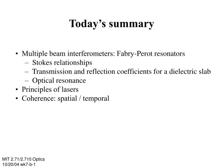
Today’s summary. • Multiple beam interferometers: Fabry-Perot resonators – Stokes relationships – Transmission and reflection coefficients for a dielectric slab – Optical resonance • Principles of lasers • Coherence: spatial / temporal . MIT 2.71/2.710 Optics

E N D
Today’s summary • Multiple beam interferometers: Fabry-Perot resonators – Stokes relationships – Transmission and reflection coefficients for a dielectric slab – Optical resonance • Principles of lasers • Coherence: spatial / temporal MIT 2.71/2.710 Optics 10/20/04 wk7-b-1
Fabry-Perot interferometers MIT 2.71/2.710 Optics 10/20/04 wk7-b-2
Relation between r, r’and t, t’ air glass air glass Proof: algebraic from the Fresnel coefficients or using the property of preservation of the field properties upon time reversal Stokes relationships MIT 2.71/2.710 Optics 10/20/04 wk7-b-3
Proof using time reversal air glass air glass MIT 2.71/2.710 Optics 10/20/04 wk7-b-4
Fabry-Perot interferometers reflected transmitted incident Resonance condition: reflected wave = 0 ⇔ all reflected waves interfere destructively wavelength in free space refractive index MIT 2.71/2.710 Optics 10/20/04 wk7-b-5
Calculation of the reflected wave incoming transmitted transmitted reflected reflected transmitted reflected transmitted reflected transmitted reflected air glass air MIT 2.71/2.710 Optics 10/20/04 wk7-b-6
Calculation of the reflected wave Use Stokes relationships MIT 2.71/2.710 Optics 10/20/04 wk7-b-7
Transmission & reflection coefficients reflection coefficient transmission coefficient MIT 2.71/2.710 Optics 10/20/04 wk7-b-8
Transmission & reflection vs path Transmission Reflection Path delay Path delay Reflection Transmission Path delay Path delay MIT 2.71/2.710 Optics 10/20/04 wk7-b-9
Fabry-Perot terminology free Spectral range band width Transmission coefficient resonance frequencies Frequency v MIT 2.71/2.710 Optics 10/20/04 wk7-b-10
Fabry-Perot terminology FWHM Bandwidth is inversely proportional to the finesse F (or quality factor) of the cavity Transmission coefficient free spectral range bandwidth finesse MIT 2.71/2.710 Optics 10/20/04 wk7-b-11
Spectroscopy using Fabry-Perot cavity Goal: to measure the specimen’s absorption as function of frequency ω Experimental measurement principle: Scanning stage (controls cavity length L ) Spectrum of light beam is modified by substance Light beam of known spectrum Power meter Transparent windows Container withspecimen to be measured Partially-reflecting mirrors (FP cavity) MIT 2.71/2.710 Optics 10/20/04 wk7-b-12
Spectroscopy using Fabry-Perot cavity Goal: to measure the specimen’s absorption as function of frequency ω Experimental measurement principle: Electro-optic (EO) modulator (controls refr. Index n) Spectrum of light beam is modified by substance Light beam of known spectrum Power meter Transparent windows Container withspecimen to be measured Partially-reflecting mirrors (FP cavity) MIT 2.71/2.710 Optics 10/20/04 wk7-b-13
Spectroscopy using Fabry-Perot cavity Fabry–Perot transmissivity Unknown spectrum Sample measured: MIT 2.71/2.710 Optics 10/20/04 wk7-b-14
Spectroscopy using Fabry-Perot cavity aaaFabry–Perot transmissivity Unknown spectrum Sample measured: MIT 2.71/2.710 Optics 10/20/04 wk7-b-15
Spectroscopy using Fabry-Perot cavity aaaFabry–Perot transmissivity Unknown spectrum Sample measured: MIT 2.71/2.710 Optics 10/20/04 wk7-b-16
Spectroscopy using Fabry-Perot cavity unknown spectrum width should not exceed the FSR aaaFabry–Perot transmissivity Unknown spectrum Sample measured: MIT 2.71/2.710 Optics 10/20/04 wk7-b-17
Spectroscopy using Fabry-Perot cavity aaaFabry–Perot transmissivity spectral resolution is determined by the cavity bandwidth Unknown spectrum Sample measured: MIT 2.71/2.710 Optics 10/20/04 wk7-b-18
Lasers MIT 2.71/2.710 Optics 10/20/04 wk7-b-19
Absorption spectra Atmospheric transmission human vision MIT 2.71/2.710 Optics 10/20/04 wk7-b-20
Semi-classical view of atom excitations Energy Atom in ground state Energy Atom in excited state MIT 2.71/2.710 Optics 10/20/04 wk7-b-21
Light generation Energy excited state equilibrium: most atoms in ground state ground state MIT 2.71/2.710 Optics 10/20/04 wk7-b-22
Light generation Energy excited state A pump mechanism (e.g. thermal excitation or gas discharge) ejects some atoms to the excited state ground state MIT 2.71/2.710 Optics 10/20/04 wk7-b-23
Light generation Energy excited state The excited atoms radiatively decay, emitting one photon each ground state MIT 2.71/2.710 Optics 10/20/04 wk7-b-24
Light amplification: 3-level system Energy Super-excited state excited state ground state equilibrium: most atoms in ground state; note the existence of a third, “super-excited” state MIT 2.71/2.710 Optics 10/20/04 wk7-b-25
Light amplification: 3-level system Energy Super-excited state excited state Utilizing the super-excited state as a short-lived “pivot point,” the pump creates a population inversion ground state MIT 2.71/2.710 Optics 10/20/04 wk7-b-26
Light amplification: 3-level system Energy Super-excited state excited state ground state When a photon enters, ... MIT 2.71/2.710 Optics 10/20/04 wk7-b-27
Light amplification: 3-level system Energy Super-excited state excited state When a photon enters, it “knocks” an electron from the inverted population down to the ground state, thus creating a new photon. This amplification process is called stimulated emission ground state MIT 2.71/2.710 Optics 10/20/04 wk7-b-28
Light amplifier Gain medium (e.g. 3-level system w population inversion) MIT 2.71/2.710 Optics 10/20/04 wk7-b-29
Light amplifier w positive feedback Gain medium (e.g. 3-level system w population inversion) When the gain exceeds the roundtrip losses, the system goes into oscillation MIT 2.71/2.710 Optics 10/20/04 wk7-b-30
Laser initial photon Gain medium (e.g. 3-level system w population inversion) • Partially • reflecting • mirror Light Amplification through Stimulated Emission of Radiation MIT 2.71/2.710 Optics 10/20/04 wk7-b-31
Laser amplified once initial photon Gain medium (e.g. 3-level system w population inversion) • Partially • reflecting • mirror Light Amplification through Stimulated Emission of Radiation MIT 2.71/2.710 Optics 10/20/04 wk7-b-32
Laser amplified once initial photon Gain medium (e.g. 3-level system w population inversion) reflected • Partially • reflecting • mirror Light Amplification through Stimulated Emission of Radiation MIT 2.71/2.710 Optics 10/20/04 wk7-b-33
Laser amplified once initial photon Gain medium (e.g. 3-level system w population inversion) reflected amplified twice • Partially • reflecting • mirror Light Amplification through Stimulated Emission of Radiation MIT 2.71/2.710 Optics 10/20/04 wk7-b-34
Laser amplified once initial photon Gain medium (e.g. 3-level system w population inversion) reflected output amplified twice reflected • Partially • reflecting • mirror Light Amplification through Stimulated Emission of Radiation MIT 2.71/2.710 Optics 10/20/04 wk7-b-35
Laser amplified once initial photon Gain medium (e.g. 3-level system w population inversion) reflected output amplified twice reflected amplified again etc. • Partially • reflecting • mirror Light Amplification through Stimulated Emission of Radiation MIT 2.71/2.710 Optics 10/20/04 wk7-b-36
Confocal laser cavities diffraction angle waist w0 Beam profile: 2D Gaussian function “TE00mode” MIT 2.71/2.710 Optics 10/20/04 wk7-b-37
Other “transverse modes” (usually undesirable) MIT 2.71/2.710 Optics 10/20/04 wk7-b-38
Types of lasers • Continuous wave (cw) • Pulsed – Q-switched – mode-locked • Gas (Ar-ion, HeNe, CO2) • Solid state (Ruby, Nd:YAG, Ti:Sa) • Diode (semiconductor) • Vertical cavity surface-emitting lasers –VCSEL–(also sc) • Excimer(usually ultra-violet) MIT 2.71/2.710 Optics 10/20/04 wk7-b-39
CW (continuous wave lasers) Laser oscillation well approximated by a sinusoid Typical sources: • Argon-ion: 488nm (blue) or 514nm (green); power ~1-20W • Helium-Neon (HeNe): 633nm (red), also in green and yellow; ~1-100mW • doubled Nd:YaG: 532nm (green); ~1-10W Quality of sinusoid maintained over a time duration known as “coherence time” tc Typical coherence times ~20nsec (HeNe), ~10μsec (doubled Nd:YAG) MIT 2.71/2.710 Optics 10/20/04 wk7-b-40
Two types of incoherence temporal incoherence spatial incoherence matched paths point source Michelson interferometer Young interferometer poly-chromatic light (=multi-color, broadband) mono-chromatic light (= single color, narrowband) MIT 2.71/2.710 Optics 10/20/04 wk7-b-41
Two types of incoherence temporal incoherence spatial incoherence matched paths point source • waves with equal paths • but from different points • on the wave front do not interfere • waves from unequal paths • do not interfere MIT 2.71/2.710 Optics 10/20/04 wk7-b-42
Coherent vs incoherent beams Mutually coherent: superposition field amplitude is described by sum of complex amplitude Mutually incoherent: superposition field intensity is described by sum of intensities (the phases of the individual beams vary randomly with respect to each other; hence, we would need statistical formulation to describe them properly — statistical optics) MIT 2.71/2.710 Optics 10/20/04 wk7-b-43
Coherence time and coherence length ‧much shorter than “coherence length” ctc Sharp interference fringes Intensity • incoming • laser • beam ‧much longer than “coherence length” ctc no interference Michelson interferometer Intensity MIT 2.71/2.710 Optics 10/20/04 wk7-b-44
Coherent vs incoherent beams Coherent: superposition field amplitude is described by sum of complex amplitudes Incoherent: superposition field intensity is described by sum of intensities (the phases of the individual beams vary randomly with respect to each other; hence, we would need statistical formulation to describe them properly — statistical optics) MIT 2.71/2.710 Optics 10/20/04 wk7-b-45
Mode-locked lasers Typical sources: Ti: Sa lasers (major vendors: Coherent, Spectra Phys.) Typical mean wavelengths: 700nm –1.4μm (near IR) can be doubled to visible wavelengths or split to visible + mid IR wavelengths using OPOs or OPAs (OPO=optical parametric oscillator; OPA=optical parametric amplifier) Typical pulse durations: ~psec to few fsec (just a few optical cycles) Typical pulse repetition rates (“rep rates”): 80-100MHz Typical average power: 1-2W; peak power ~MW-GW MIT 2.71/2.710 Optics 10/20/04 wk7-b-46
Overview of light sources non-Laser Laser Thermal: polychromatic, spatially incoherent (e.g. light bulb) Continuous wave (or cw): strictly monochromatic, spatially coherent (e.g. HeNe, Ar+, laser diodes) Gas discharge: monochromatic, spatially incoherent (e.g. Na lamp) Pulsed: quasi-monochromatic, spatially coherent (e.g. Q-switched, mode-locked) Light emitting diodes (LEDs): monochromatic, spatially incoherent ~nsec ~psec to few fsec pulse duration mono/poly-chromatic = single/multi color MIT 2.71/2.710 Optics 10/20/04 wk7-b-47