Download
1 / 26
260 likes | 379 Views
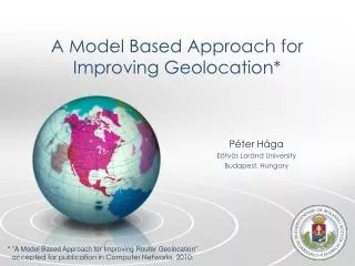
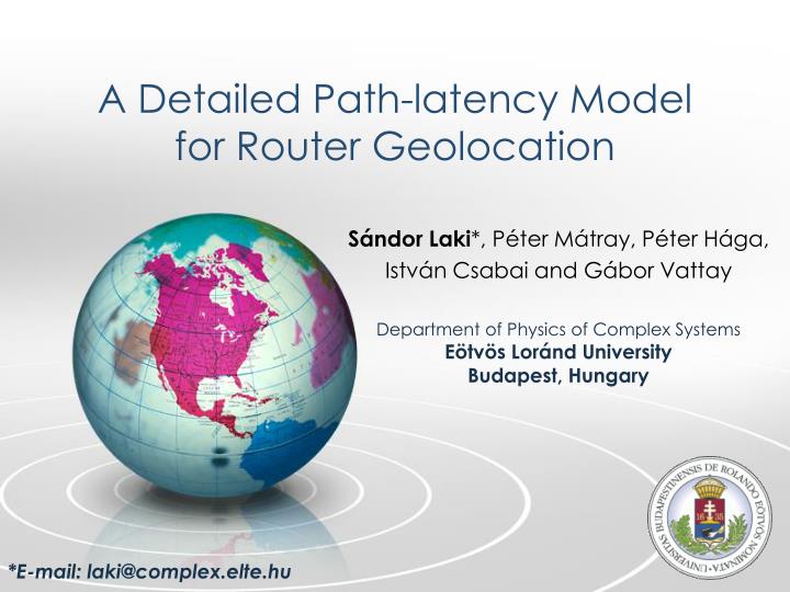
A Detailed Path-latency Model for Router Geolocation. Sándor Laki *, Péter Mátray , Péter Hága, István Csabai and Gábor Vattay. Department of Physics of Complex Systems Eötvös Loránd University Budapest, Hungary. *E-mail: laki@ complex.elte.hu. Agenda. Introduction

E N D
A DetailedPath-latencyModelforRouterGeolocation Sándor Laki*, Péter Mátray, Péter Hága, István Csabai and Gábor Vattay Department of PhysicsofComplex Systems Eötvös Loránd University Budapest, Hungary *E-mail: laki@complex.elte.hu
Agenda • Introduction • Path-latencyModel • Velocity of SignalPropagationin Network • GeographicConstraints • Data Collection • Performance Analysis • Summary
Motivation • Locationinformationcan be usefultobothprivate and corporeteusers • Targetedadvertisingonthe web • Restrictedcontentdelivery • Location-basedsecuritycheck • Web statistics • Scientificapplications • Measurementvisualization • Network diagnostics
Geolocationin General • Passivegeolocation • Extractinglocationinformationfromdomainnames • DNS and WhoISdatabases • Commercialdatabases • MaxMind, IPligence, Hexasoft • Large and geographicallydispersed IP blockscan be allocatedto a singleentity • Activegeolocation • Activeprobing • Measurementnodeswithknownlocations • GPS-likemultilateration (CBG)
MeasurementBasedGeolocation • Activemeasurements • Network Delays • Delayscan be transformedtogeographicdistance • RoundTrip Time (ping) • One-waydelay • Effects of over and underestimation • Topology • Network-pathdiscovery • Traceroutewith fixed port pairs • Interfaceclustering • Mercator, etc.
PresentationOutline • Introduction • Path-latencyModel • Velocity of SignalPropagationin Network • GeographicConstraints • Data Collection • Performance Analysis • Summary
Whydoweneed a latencymodel? • The basis of activemethods is totransformdelaystogeographicdistance • The modelaimstodecomposethe overall packetdelaytolinkwisecomponents • Approximatingpropagationdelaysalong a networkpath • leadsto more precisedistanceestimations...
Modelling PacketDelays • A packetdelay (d) can be dividedinto… • Queuingdelay (Dq) • Processingdelay (Dpc) • Transmissiondelay (Dtr) • Propagationdelay (Dpg) Onlythepropagationcomponent has roleinthegeolocation n0 n1 n2 nH • A givenpath: • The overall packetdelayfor a networkpath (s=n0 and d=nH): …
HowtoEstimatePropagationDelays • Assumptionsinthemodel • No queuing(Dq= 0) • The per-hopprocessing and transmissiondelayscan be approximatedby a globalconstant(dh) • dh = Dpc+ Dtr • Basedontheliterature and ourobservations: • dh = 100s The one-waypropagationdelayalong a givenpath:
An Extra Cost - ICMP Generation Time • Incase of ICMP based RTT measurementsan extra delayappearsatthetargetnode • ICMP EchoReplyGeneration Time (Dg) • The overall RoundTripDelay: Is itpossibletomeasurethisDgdelaycomponent? Yes, there’s a way…
ICMP Generation Times Dg = 300 s toavoiddistanceunderestimation Less than 1%
Presentationoutline • Introduction • Path-latencyModel • Velocity of SignalPropagationin Network • GeographicConstraints • Data Collection • Performance Analysis • Summary
DistanceApproximation • An upperapproximation of geographicaldistancefromsourcestodestinationd: Network cablesnotrunningstraightduetoseveralreasons • where r is thevelocity of signalpropagationinnetwork [incunits] d Physicalpropertiesof thenetworkcables s
SignalPropagationin Network And theaveragevaluewas 0.27 The maximum velocitywemeasuredinnetworkwas 0.47! The maximum valuewasusedtoavoiddistanceunderestimation The velocity of signalpropagationin a coppercable is ~0.66-0.7!
Presentationoutline • Introduction • Path-latencyModel • Velocity of SignalPropagationin Network • GeographicConstraints • Data Collection • Performance Analysis • Summary
SolvingGeolocation • Defininggeographicconstraints • Wearelookingfor a locationsetwherealltheconstrainscometrue • Definingtheoverall tensioninthesystem • A costfunction • Byminimizingthisfunctiontheproblemcan be solved • Non-convexoptimizationproblem • Wellknownsolutionsinsensornetworks
Round-Trip Time Constraint • Usingpath-latencymodel • Round-trippropagationdelayfrom a landmark • Upperapproximation of one-waypropagationdelay The node to be localized t L Landmark withknownlocation
One-wayDelayConstraint • A novelconstraintfor a networkpathbetweentwolandmarks • Limiting thegeographiclength of a givennetworkpath • High-precision OWD measurements n2 L2 n3 L1 n1
Presentationoutline • Introduction • Path-latencyModel • Velocity of SignalPropagationin Network • GeographicConstraints • Data Collection • Performance Analysis • Summary
An Award-winningTestbed • European TrafficObservatoryMeasurementInfrastruCture(etomic) was created in 2004-05 within the Evergrow Integrated Project. • Open and publictestbedforresearchersexperimentingthe Internet • 18 GPS synchronizedactiveprobingnodes • EquipedwithEndace DAG cards • High-precisionend-to-endmeasurements • Scheduledexperiments • NO SLICES • Youowntheresources duringthe experimentation Best Testbed Award www.etomic.org
Presentationoutline • Introduction • Path-latencyModel • Velocity of SignalPropagationin Network • GeographicConstraints • Data Collection • Performance Analysis • Summary
Performance Analysis Geo-Rh Meanerror: 251 km Max. error: 699 km StdDev: 205 km Geo-RhOL Meanerror: 149 km Max. error: 312 km StdDev: 104 km Geo-R Meanerror: 305 km Max. error: 878 km StdDev: 236 km
Presentationoutline • Introduction • Path-latencyModel • Velocity of SignalPropagationin Network • GeographicConstraints • Data Collection • Performance Analysis • Summary
Summary • Estimatingpropagationdelays more precisely • Separation of propagation and per-hopdelaysinthe overall packetlatency • Velocity of signalpropagationinnetwork is muchsmallerthanweassumedbeforeduetocurvatures • The novelone-waydelayconstraintsimprovetheaccuracy of routergeolocationsignificantly • Nowadaysthesemeasurementsareavailablein a few NGN testbeds (ETOMIC, newOneLab-2nodes, etc.) • Plansforfutureextensions • The methodcan be combinedwithpassivetechniques • Improvinglatencymodel
OneLab2 - The NextGeneration of ETOMIC • OneLab2 sites: • ≥2 PlanetLabnodes • New features • Dummybox • WiFiaccess • UMTS, WiMax… • 1 ETOMIC2-COMO • integratednode • Highprecision e2e measurements • ARGOS meas. card • availableviaETOMIC’s CMS • 1 APE box • A lightweight • measurementtool ETOMIC www.etomic.org OneLab2 www.onelab.eu www.etomic.org
Thankyouforyourattention! Contact: laki@complex.elte.hu This work was partially supported by the National Office for Research and Technology (NAP 2005/ KCKHA005) and the EU ICT OneLab2 Integrated Project (Grant agreement No.224263).