Download
1 / 53
550 likes | 761 Views
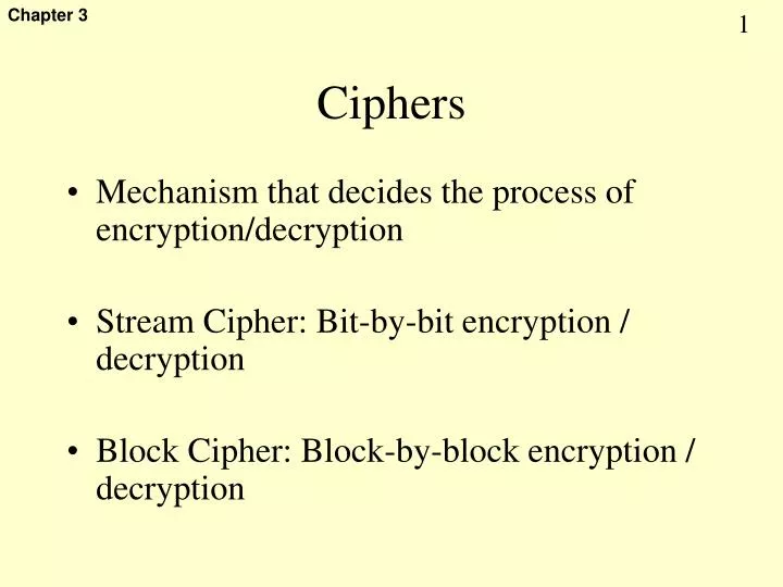
Ciphers. Mechanism that decides the process of encryption/decryption Stream Cipher: Bit-by-bit encryption / decryption Block Cipher: Block-by-block encryption / decryption. Algorithm Types. Block Ciphers. Stream Ciphers. Types of Cipher. Fig 3.1. Basic operations upon string of 0/1.

E N D
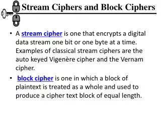
Ciphers • Mechanism that decides the process of encryption/decryption • Stream Cipher: Bit-by-bit encryption / decryption • Block Cipher: Block-by-block encryption / decryption
Algorithm Types Block Ciphers Stream Ciphers Types of Cipher Fig 3.1
Basic operations upon string of 0/1 • View text as Coded Word • XOR (⊕) • Transposition • Logical Operations (A∩B,…) • View text as blocks (Block Number) • +,-,*,/ • Finite Field (under Modular) • Exponentiation (under Modular) • …
XOR operation ⊕ • XOR operation ⊕: • Encrypted: M ⊕ K= C • Decrypted: C ⊕ K= M • Math. Notation: • Encryption: M ⊕ K C • Decryption: C ⊕ K M
Basic of stream cipher • Message M comes in bit strings • Key bit strings are generated from a key K • Encryption: • Cipher C are basically an bit XOR operation between message bit strings and key bit strings (generated from key K) • Decryption: • Message M comes from an bit XOR operation between Cipher C strings and key bit strings (generated from key K)
Encrypt/Decrypt with XOR Sender (A) Receiver (B) Cipher text Cipher text Network …01101 …01101 …10100 …10100 Plain text Plain text 10011… 10011…
A serial of bit sequence output 1 0 0 Pseudo random generator + Key How to generate the key bit sequence by a key Concept LFSR, Linear Feedback shift register
Program for LFSR • Parameter: • Unsigned long shiftRegister • shiftRegister = input_key • Procedure: • Output shiftRegister&0x0000001 ; • shiftRegister = ( (shiftRegister >>2) ^ (shiftRegister >>1) & 0x00000001)<<31) | (shiftRegister >>1);
Stream Cipher basic (XOR Blockbit level) In normal format In binary format Plain text F4 0100011000110100 + the key 0001010100001111 S; 0101001100111011 Cipher text
Block Cipher • Message are chocked into numbers of block Each block are encrypted with block ciphers • Block between block are operated with one of the four modes (ECB,CBC,OFB, OCB). • Known Block Ciphers: • DES, triple DES,IDEA, RC5, Blowfish, AES
Sender (A) Receiver (B) Network Cipher text Cipher text Plain text Plain text Encrypt with symmetric key Decrypt with symmetric key Symmetric Key Cryptography Fig 3.15
Data Encryption Standard (DES) • History • 1977 published by National Institute of Standard and Technology, USA • Based on IBM Lucifer cipher and NSA • Specification: • Uses a 56-bit key (among 64-bit), and map a 64-bit input block into a 64-bit output block. • Theory basics: • Input permutation, key introduce bit string (s-box), XOR • Comment: • DES is efficient to implement in hardware but relative slow in software. For example, a 500-MIPS CPU can encrypt at 30 Koctets per second.
64-bit Plain text 64-bit Plain text 64-bit Plain text 56-bit Key 56-bit Key 56-bit Key DES DES DES 64-bit Cipher text 64-bit Cipher text 64-bit Cipher text Block n Block 2 Block 1 Conceptual View of DES Fig 3.16
Plain text (64 bits) Step 1 Initial Permutation (IP) Step 2 Step 3 LPT RPT 16 rounds 16 rounds Keyi Key Step 4 Final Permutation (FP) Step 5 Cipher text (64 bits) Step 6 Broad Level Steps in DES Fig 3.19
Initial permutation (IP) • Input 64-bit after bit position change (IP) produces 64-bit output Means: Output bit 1 from bit 58, bit 2 from bit 50, bit 3 from 42,…
64-bit input 56-bit key Initial Permutation Generate 16 per-round keys 48-bit K1 Round 1 Round 2 48-bit K2 48-bit K16 Round 16 Swap left and right halves Final Permutation 64-bit output Board level include the master Key
The Mangler Function • Two inputs: 32-bit plus 48-bit subkey • Output: 32-bit • Operations: • Step 1: 32-bit are expanded into 48-bit • Step 2: the expanded 48-bit are XORed with the 48-bit subkey • Step 3: the 48-bit result are divide into 8 blocks with 6 bits. • Step 4: each block are lookup into the S-box to generate the 4 bit • Step 5: the result 32-bit are then permutated to generate the 32 output.
S-box 1 S-box 8 S-box 2 32-bit(RPT) Expansion permutation 48-bit XOR 48-bit(subkey) 48-bit divide into 8 6-bit blocks 32-bit P-Box permutation 32-bit
Expansion permutation P-box permutation
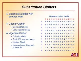
S-box(1~8) S-box 1 0000 0001 0010 0011 0100 0101 0110 1111 00 01 10 11 For example: bit 101101, table look up 11 0110
How Sub key generate from Key • Input : 64 bits • Output: 48 bits x 16 (round 1~16) • Steps: • 1) 64 bits to 56 bits, and the 56 bits is divide into 2 halves, each of 28 bits, called C and D. (through a discard permutation) • 2) each of 28 bits are rotated (round 1,2,9,1nd 16 are 1bit, and other are 2-bit) • 3) from the 2 halves, among the 56 bits only 48 bits are got through compression permutation
Discard permutation compression permutation
Initial and Final Permutation After IP-1, bit 58 comes from bit 1, bit 50 come from bit 2, … After IP, bit 1 comes from bit 58, bit 2 come from bit 50, …bit 9 come from bit 60 Reason: first 8bit spread into the 8th bits of each of the octets.
Generating the Pre-Round Keys 1. Among 64-bit key, only 56-bit is effective. 2. These bits are permutated. (bit 1 comes from bit 57) 3. The permutated 56-bit output is divides into two 28-bit values, called C0 and D0.
4. Each C and D are rotated left (round 1,2,9,1nd 16 are 1bit, and other are 2-bit) 5. After rotated, the output of C and D are 1) feedback for next C and D, 2) 28-bit of C is to permutated into 24-bit left part of subkey K, 3) 28-bit of D into 24-bit right part of subkey
Mathematics‘ notation on Block cipher Like DES • For plain text m, encrypted with key K1, is denoted as: Ek1[m] (m)k1 if encrypt / decrypt operation is obvious. • For a cipher text c, decrypted with key K1, is denoted as: Dk1[c] (c)k1 if encrypt / decrypt operation is obvious. i.e., Dk1[Ek1[m] ] = m ((m)k1 )k1= m
RC5 • Developed by Ron Rivest • Quite fast, flexibility (security vs speed) • Almost no memory for execution: • Suitable for PDA, smart card, ..
Basic principles • Variable lengths • Block size (word bits and 2-word blocks), number of rounds and number of 8-bit bytes (octets) of the key • Particular RC5 instance should be assigned, denoted as RC5-w/r/b, e.g., RC5-32/12/16 means 64-bit block, 12 round, and 16x8 bits key
First, divide the original plain text into two blocks of equal size. Call them as A and B. Add A and S[0] to produce C. Add B and S[1] to produce D. Note: First perform all the left-hand side steps, and then come to the right hand side steps, as indicated by the step numbers. 4. XOR D and F to produce G. 1. XOR C and D to produce E. 2. Circular-left shift E by D bits. 5. Circular-left shift G by F bits. 3. Add E and S[2i] to produce F. 6. Add G and S[2i + 1] to produce H. Increment i by 1. Call F as C (i.e. C = F) Call H as D (i.e. D = H) No Check: Is i > r? Yes Stop Encryption using RC5 Fig 3.54
RC5 Encryption • A = A + S[0] • B = B + S[1] • For i = 1 to r • A = ((A XOR B) <<< B) + S[2i] • B = ((B XOR A) <<< A) + S[2i + 1] • Next i Fig 3.63
RC5 Decryption • For i = r to 1 step –1 (i.e. decrement i each time by 1) • B = ((B – S[2i + 1]) >>> A) XOR A • A = ((A – S[2i]) >>> B) XOR B • Next i • B = B – S[1] • A = A – S[0] Fig 3.64
Sub-key creation in RC5 • 8-bit as a unit • First, the key is put to array L, denoted as, L[0], L[1],…, L[b-1] • Second, generate the array S, by using two constant P (0xb7e15163)and Q (0x9e3779b9), up to 2 times round plus 1, S[0], S[1],…S[2r+1] • Third, Mixing array L and S, to produce the final subkey array S
Array S generated s[0]=p For i=1 to 2r+1 s[i]=(s[i-1]+Q) mod 2^32 Next i Mix Array S and L to generate S i=j=0 A=B=0 Do 3n times (n =max(2r+1, b)) A=s[i]=(s[i]+A+B)<<<3 B=L[j]=(L[j]+A+B)<<<(A+B) i = (i+1) mod 2(r+1) j= (j+1) mod b end-do
International Data Encryption Algorithm (IDEA) • 1991 by Lai and Massey in Zuria. • 64-bit block of plaintext into 64-bit block of cipher text using 128-bit key. • Two main operations: • Module addition based on mod 216. • Module multiplication based on mod 216 +1
Basic unit in IDEA Round D1 D2 D3 D4 k3 k1 k4 k2 W1 W2 W3 W4 Questions: How to decrypt the basic unit
Operation modes for block ciphers • Operation modes: • Block between block operation • Four modes: • ECS (Electronic Code Book) • CBC (Cipher Block Chaining) • CFB (Cipher Feedback) • OFB (Output Feedback) • Counter Mode
Plain text block n Plain text block 2 Plain text block 1 Encrypt Encrypt Encrypt Key Key Key Cipher text block n Cipher text block 2 Cipher text block 1 Step n Step 2 Step 1 Encryption in ECB Mode Fig 3.6
Cipher text block n Cipher text block 2 Cipher text block 1 Decrypt Decrypt Decrypt Key Key Key Plain text block n Plain text block 2 Plain text block 1 Step n Step 2 Step 1 Decryption in ECB Mode Fig 3.7
FOUR _AND_ FOUR Plain text Encrypt Encrypt Encrypt VFa% *yT1x VFa% Cipher text (a) The Encryption Process at the sender’s end VFa% *yT1x VFa% Cipher text Decrypt Decrypt Decrypt FOUR _AND_ FOUR Plain text (b) The Decryption Process at the receiver’s end ECB Example Fig 3.4
Plain text block n Plain text block 2 Plain text block 1 IV XOR XOR XOR Encrypt Key Encrypt Encrypt Key Key Cipher text block n Cipher text block 2 Cipher text block 1 Step n Step 2 Step 1 Encryption in CBC Mode Fig 3.8
Cipher text block n Cipher text block 2 Cipher text block 1 Decrypt Key Decrypt Decrypt Key Key IV XOR XOR XOR Plain text block n Plain text block 2 Plain text block 1 Step n Step 2 Step 1 Decryption in CBC Mode Fig 3.9
IV (Shift register) IV (Shift register) IV (Shift register) Encrypt Encrypt Key Key Encrypt Key Take just the leftmost 8 bits Take just the leftmost 8 bits Take just the leftmost 8 bits XOR XOR XOR Plain text j bits Plain text j bits Plain text j bits Cipher text j bits Cipher text j bits Cipher text j bits Encryption in CFB Mode Fig 3.13
IV (Shift register) IV (Shift register) IV (Shift register) Encrypt Encrypt Key Key Encrypt Key Take just the leftmost 8 bits Take just the leftmost 8 bits Take just the leftmost 8 bits XOR XOR XOR Plain text j bits Plain text j bits Plain text j bits Cipher text j bits Cipher text j bits Cipher text j bits Encryption in OFB Mode Fig 3.14
Modified Versions of DES • Double DES: Perform DES twice with two different keys • Triple DES with Three Different Keys • Triple DES with Two Different Keys
Cipher Text Cipher Text Original Plain Text Encrypt Encrypt K1 K2 Double DES Encryption Fig 3.36
Cipher Text Cipher Text Original Plain Text Decrypt Decrypt K2 K1 Double DES Decryption Fig 3.37
EK1(P) T = EK1(P) EK2(EK1(P)) C = EK2(EK1(P)) C Temporary result (T) P Encrypt Encrypt K1 K2 Double DES Expressed Subject to: meet-in-the-middle attack Step 1: store all possible EK1(P) Step 2: decrypt c with all possible key value DK2(C) Step 3: find a match value at step 1 and 2.
Final Cipher Text Cipher Text 1 Original Plain Text Encrypt Cipher Text 2 Encrypt Encrypt K1 K3 K2 Triple DES Fig 3.41