Download
1 / 25
260 likes | 417 Views
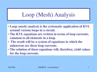
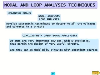
LOOP ANALYSIS. VSR. Loop Analysis. Nodal analysis was developed by applying KCL at each non-reference node. Loop analysis is developed by applying KVL around loops in the circuit. Loop (mesh) analysis results in a system of linear equations which must be solved for unknown currents.

E N D
LOOP ANALYSIS VSR VSR E&E Dept
Loop Analysis • Nodal analysis was developed by applying KCL at each non-reference node. • Loop analysis is developed by applying KVL around loops in the circuit. • Loop (mesh) analysis results in a system of linear equations which must be solved for unknown currents. VSR E&E Dept
Example: A Summing Circuit • The output voltage V of this circuit is proportional to the sum of the two input voltages V1 and V2. • This circuit could be useful in audio applications or in instrumentation. • The output of this circuit would probably be connected to an amplifier. VSR E&E Dept
Summing Circuit Solution: Vout = (V1 + V2)/3 1kW 1kW + + – + – V1 Vout 1kW V2 – VSR E&E Dept
Steps of Mesh Analysis 1. Identify mesh (loops). 2. Assign a current to each mesh. 3. Apply KVL around each loop to get an equation in terms of the loop currents. 4. Solve the resulting system of linear equations. VSR E&E Dept
Identifying the Meshes 1kW 1kW 1kW + – Mesh 1 Mesh 2 + – V1 V2 VSR E&E Dept
Steps of Mesh Analysis 1. Identify mesh (loops). 2. Assign a current to each mesh. 3. Apply KVL around each loop to get an equation in terms of the loop currents. 4. Solve the resulting system of linear equations. VSR E&E Dept
Assigning Mesh Currents 1kW 1kW 1kW + – + – V1 V2 I1 I2 VSR E&E Dept
Steps of Mesh Analysis 1. Identify mesh (loops). 2. Assign a current to each mesh. 3. Apply KVL around each loop to get an equation in terms of the loop currents. 4. Solve the resulting system of linear equations. VSR E&E Dept
VR + – Voltages from Mesh Currents VR + – I2 R R I1 I1 VR = I1R VR = (I1 -I2 ) R VSR E&E Dept
1kW 1kW 1kW + – + – V1 V2 I1 I2 KVL Around Mesh 1 -V1 + I1 1kW + (I1 - I2) 1kW = 0 I1 1kW + (I1 - I2) 1kW = V1 VSR E&E Dept
1kW 1kW 1kW + – + – V1 V2 I1 I2 KVL Around Mesh 2 (I2 - I1) 1kW + I2 1kW + V2 = 0 (I2 - I1) 1kW + I2 1kW = -V2 VSR E&E Dept
Steps of Mesh Analysis 1. Identify mesh (loops). 2. Assign a current to each mesh. 3. Apply KVL around each loop to get an equation in terms of the loop currents. 4. Solve the resulting system of linear equations. VSR E&E Dept
Matrix Notation • The two equations can be combined into a single matrix/vector equation. VSR E&E Dept
Solving the Equations Let: V1 = 7V and V2 = 4V Results: I1 = 3.33 mA I2 = -0.33 mA Finally Vout = (I1 - I2) 1kW = 3.66V VSR E&E Dept
2kW 2mA 1kW + – 12V 2kW 4mA I0 Another Example VSR E&E Dept
1. Identify Meshes 2kW Mesh 3 2mA 1kW + – Mesh 1 2kW Mesh 2 12V 4mA I0 VSR E&E Dept
I3 I1 I2 2. Assign Mesh Currents 2kW 2mA 1kW + – 2kW 12V 4mA I0 VSR E&E Dept
Current Sources • The current sources in this circuit will have whatever voltage is necessary to make the current correct. • We can’t use KVL around the loop because we don’t know the voltage. • What to do? VSR E&E Dept
Current Sources • The 4mA current source sets I2: • I2 = -4 mA • The 2mA current source sets a constraint on I1 and I3: • I1 - I3 = 2 mA • We have two equations and three unknowns. Where is the third equation? VSR E&E Dept
The Supermesh! The Supermesh does not include this source! 2kW The Supermesh surrounds this source! 2mA I3 1kW + – 2kW 12V 4mA I1 I2 I0 VSR E&E Dept
KVL Around the Supermesh -12V + I3 2kW + (I3 - I2)1kW + (I1 - I2)2kW = 0 I3 2kW + (I3 - I2)1kW + (I1 - I2)2kW = 12V VSR E&E Dept
Matrix Notation • The three equations can be combined into a single matrix/vector equation. VSR E&E Dept
Solution I1 = 1.2 mA I2 = -4 mA I3 = -0.8 mA I0 = I1 - I2 = 5.2 mA VSR E&E Dept
THANK YOU VSR E&E Dept