Download
1 / 50
500 likes | 685 Views
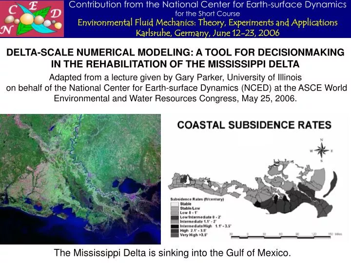
DELTA-SCALE NUMERICAL MODELING: A TOOL FOR DECISIONMAKING IN THE REHABILITATION OF THE MISSISSIPPI DELTA Adapted from a lecture given by Gary Parker, University of Illinois

E N D
DELTA-SCALE NUMERICAL MODELING: A TOOL FOR DECISIONMAKING IN THE REHABILITATION OF THE MISSISSIPPI DELTA Adapted from a lecture given by Gary Parker, University of Illinois on behalf of the National Center for Earth-surface Dynamics (NCED) at the ASCE World Environmental and Water Resources Congress, May 25, 2006. The Mississippi Delta is sinking into the Gulf of Mexico.
THE PROBLEMS OF THE MISSISSIPPI DELTA AND THE RISK TO NEW ORLEANS WERE WELL-KNOWN LONG BEFORE HURRICANE KATRINA Scientific American, October, 2001
THE MISSISSIPPI DELTA FALLS WITHIN THE CLASS OF FANS AND FAN-DELTAS The Nile Delta, Egypt. From NASA The Okavango Inland Fan, Botswana. From NASA
THE FAN-DELTA AT THE MOUTH OF THE YELLOW RIVER IS A GOOD ILLUSTRATION Mouth of the Yellow River. From NASA.
THE PROCESSES The processes that build fans and fan-deltas are: • Channel aggradation and progradation • overbank sediment deposition as channel aggrades • delta extension as channel head progrades • channel migration or avulsion to shorter path to sea
THE ENTIRE NORTH CHINA PLAIN IS AN ALLUVIAL FAN Over thousands of years of historical time the Yellow River has repeatedly shifted between courses north and south of the Shandong peninsula. Present delta Shandong peninsula
WHAT HAPPENS WHEN HUMANS INTERFERE WITH THIS PROCESS BY BUILDING DIKES AND PREVENTING AVULSIONS? One reach of the Yellow River is perched 10 m above the surrounding North China Plain Adapted from Hu Yisan and Xu Fuling (1989)
THE KUSATSU RIVER FORMS A FAN-DELTA ON LAKE BIWA, JAPAN WHICH IS DENSELY POPULATED It has not been allowed to avulse since the 10th Century.
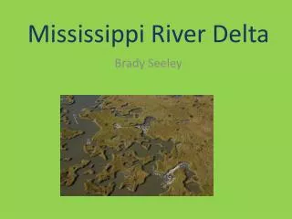
OVER GEOMORPHIC TIME THE MISSISSIPPI RIVER HAS REPEATEDLY AVULSED TO FORM NEW LOBES
Mississippi River and levees downstream of New Orleans. Subsiding fan-delta surface behind levees south of New Orleans. LIKE MANY LARGE DELTAS, THE MISSISSIPPI DELTA SUBSIDES BY COMPACTION UNDER ITS OWN WEIGHT Under natural conditions, this subsidence is balanced by overbank deposition of sediment and avulsion into low areas.
THE RIVER IS DIKED ALONG ITS ENTIRE LENGTH AND IS NOT ALLOWED TO AVULSE Sediment is either stored in-channel or funneled out to sea.
SO THE RIVER BED GETS HIGHER AND HIGHER E.G. AT THE OLD RIVER CONTROL STRUCTURE,
THE RIVER MOUTH EXTENDS FARTHER AND FARTHER INTO THE GULF OF MEXICO,
AND THE REST OF THE DELTA SUBSIDES UNDER COMPACTION, WITH NO REPLACEMENT SEDIMENT, CAUSING THE SHORELINE TO ADVANCE Fischetti (2001), Scientific American “At this rate, New Orleans will be exposed to the open sea by 2090.”
THE PROBLEM IN A NUTSHELL • The Mississippi Delta rapidly subsides by compaction under its own weight. • Under natural conditions this subsidence is balanced by overbank deposition of sediment abetted by channel avulsion. • The mud that would construct the floodplain is held behind levees and delivered out to sea. • Meanwhile the sand deposits on the channel between the levees as it elongates. • As a result, the levees and the prevention of avulsion is causing the shoreline to advance, not in geomorphic time, but in engineering time.
THE MISSISSIPPI DELTA PROJECT OF THE NATIONAL CENTER FOR EARTH-SURFACE DYNAMICS (NCED) NCED has been developing large-scale morphodynamic models to evaluate the rehabilitation of the Mississippi Delta.
HURRICANE KATRINA HIGHLIGHTED THE NEED FOR THE MISSISSIPPI DELTA PROJECT which is being conducted as as a joint effort between NCED’s Stream Restoration and Subsurface Architecture programs
The root of the problem, however is the disappearance of delta land as sediment that would replenish the sinking delta is instead channeled by dikes straight out to the Gulf of Mexico. THE MISSISSIPPI DELTA/NEW ORLEANS PROBLEM IS OFTEN THOUGHT OF AS A HURRICANE/STORM-SURGE PROBLEM This house is not in standing water because of storm surge! There is no hope of alleviating thestorm surge problem without building land.
HERE? OR HERE? CAN WE BUILD LAND BY MEANS OF A PARTIAL DIVERSION (CONTROLLED AVULSION) OF THE MISSISSIPPI RIVER?
PROOF OF CONCEPT: THE WAX LAKE DELTA During the Great Flood of 1973, the Mississippi River nearly avulsed into the Atchafalaya River and part of the Atchafalaya River avulsed into a drainage channel (Wax Lake Outlet) to form the Wax Lake Delta
THE WAX LAKE DELTA HAS BEEN BUILDING NEW LAND SINCE 1973 The Atchafalaya River has been receiving 30 ~ 60% of the sediment of the Mississippi River, and the Wax Lake Delta has been receiving about half of the sediment of the Atchafalaya River.
CAN WE CAPTURE THIS LAND BUILDING IN A NUMERICAL MODEL? A first model has been developed by NCED at the Univ. of Illinois, in cooperation with • NCED researchers at the Univ. of Minnesota (Paola) and the Massachusetts Institute of Technology (Mohrig), and • Cooperating researchers at Louisiana State Univ. (Roberts, Twilley), Univ. of Louisiana Lafayette (Meselhe), Univ. of New Orleans (McCorquodale) and Tulane Univ. (Allison).
ELEMENTS INCLUDED IN THE MODEL • Deposition of sand • Deposition of mud • Flood hydrology • Self-channelization • Channel-floodplain co- evolution • Delta progradation • Subsidence • Sea level rise
Fluvial reach • xv = downvalley coordinate on fluvial reach • Lf = reach length • Bfc = channel bankfull width on fluvial reach • Bf = floodplain width on fluvial reach • Fan-delta reach • rf = downfan radial coordinate • ru = value of rf at upstream end of fan reach • rd = rd(t) = value of rf at downstream end of fan-delta reach • = fan-delta angle Bd = r = fan-delta width Bdc = width of channel (or amalgamated channels) on fan-delta reach THE GEOMETRY
SOME ASSUMPTIONS • Sand deposits in both the channel and the floodplain, but mud deposits only in the floodplain, For each volume unit of sand deposited in the channel-floodplain complex units of mud are deposited in the channel-floodplain complex. • The channel(s) migrates or avulses across the floodplain (width Bf) or fan-delta (width Bc = r) to fill all the available space. • The channel is meandering and has sinuosity f on the fluvial reach and d on the fan-delta reach. Averaging over many bends, the relation between down-channel coordinate x and down-valley coordinate xv in the fluvial reach is given as • Where r is down-channel coordinate on the fan-delta, the corresponding relation for the fan-delta reach is
SOME ASSUMPTIONS (contd.) • The bulk porosity of the deposit in the channel-floodplain complex of the fluvial reach is pf. The corresponding value for the fan-delta is pd. • The mean elevation of the bed of the channel-floodplain complex of the fluvial reach is f; the corresponding value for the fan-delta reach is d. • Well below the surface channel-floodplain complex is a basement with elevation bf in the fluvial reach and elevation bd in the fan-delta reach. These basements are subsiding under compaction at the respective fluvial and fan-delta rates f and d, where f f bf xv
EXNER EQUATION OF SEDIMENT CONTINUITY: FLUVIAL REACH The volume flood transport rates sand and mud during floods load in m3/s are denoted as Qs and Qm, respectively. Flood intermittency is If so that e.g. IfQs = mean annual volume sand load. Sand and mud are transported down the channel(s). Only sand deposits in the channel; sand and mud deposit across the entire channel-floodplain complex. Reduce with to get
EXNER EQUATION OF SEDIMENT CONSERVATION: FLUVIAL REACH AND FAN-DELTA REACHES Fluvial reach: sediment is transported in the channel but deposited over the entire floodplain width to model long-term floodplain deposition, channel migration and avulsion. Where the subscript “f” denotes “fluvial reach”: Fan-delta reach: sediment is transported in the channel, or an amalgamation of more than one active channels, but deposited over the entire width Bd = rf of an axially symmetric fan-delta to model long-term floodplain deposition, channel migration and avulsion. The analogous form of sediment conservation, for which the subscript “d” denotes “fan-delta reach”, is:
CLOSURE FOR SELF-FORMED CHANNEL GEOMETRY Channel geometry is described using bankfull parameters. A Chezy resistance relation with constant Cz = Cf-1/2) is applied to gradually varied flow. Where Ubf denotes flow velocity at bankfull flow, the bed shear stress is given as (slide 34 of lecture on hydraulics) The sand in the streambed is characterized with a single grain size D. A constant channel-forming Shields number is assumed; recalling Qbf = UbfBbfHbf, where from slide 25 of the lecture on hydraulic geometry form* ~ 2.16. The sand transport relation is that of Engelund and Hansen (1967); reducing the relation of slide 11 of the lecture on hydraulics with Qs = Bbfqt = sand load at bankfull flow,
IS THE ASSUMPTION OF CONSTANT CHANNEL-FORMING SHIELDS NUMBER REASONABLE? The diagram below is from the lecture on bankfull hydraulic geometry
BACKWATER AT BANKFULL FLOW IN A SELF-FORMED CHANNEL The full backwater equation is (slides 34 and 25 of the lecture on hydraulics) A constant channel-forming Shields number form* implies a bankfull velocity Ubf that is constant in the downstream direction: The backwater equation applied to bankfull flow thus reduces to Where Frbf = bankfull Froude number. In low-slope sand-bed streams, Frbf2 is usually < 0.1, and can be neglected, yielding
ARE THE ASSUMPTIONS OF CONSTANT BANKFULL FLOW VELOCITY AND Frbf2 << 1 REASONABLE? We use the data of the lecture on bankfull hydraulic geometry, and define Constant not too bad! Frbf2 << 1 generally good!
BACKWATER CALCULATION FOR BANKFULL DEPTH Hbf It is useful to change the backwater calculation from down-channel coordinates r and x, respectively on the fan-delta and fluvial reach to down-fan-delta and down-valley coordinates rf and xv, where The backwater equations for the respective reaches become The calculation is performed upstream from the location of the topset-foreset break, located at r = rd(t). The elevation of standing water d(t), which may change in time to include sea level rise, must be specified at r = rd. In addition, the water surface elevation must be continuous at the junction between the fan-delta and fluvial reachs. This leads to the conditions
CALCULATION OF SAND LOAD, BANKFULL WIDTH Once Hbf is calculated everywhere, the relations below can be reduced to the following forms for the sand load Qs at bankfull flow and bankfull width:
TRANSLATION OF EXNER EQUATIONS FROM DOWN-CHANNEL COORDINATES TO DOWN-VALLEY COORDINATES Upstream boundary condition: specified feed rate of sand: Continuity condition at junction between fluvial and fan-delta reachs:
CONDITIONS AT THE DELTA FACE The topset-foreset break, which serves as a surrogate for shoreline, is located at rf = rd(t). The foreset-basement break is located at rf = rb(t). Both of these boundaries migrate outward as the delta progrades. The basement over which the delta progrades is assumed to have constant slope slope Sb in the analysis described here. The slope of avalanche Sa of the delta face is also assumed to be a prescribed constant here.
SHOCK CONDITION AT THE DELTA FACE Let fore(r) denote elevation profile on the foreset. The slope profile over the foreset is given as Now then where fan-delta slope at topset-foreset break
SHOCK CONDITION AT THE DELTA FACE Now assuming spatially constant subsidence rate d and vanishing sand transport at the base of the foreset (Qs = 0 at r = rb) integrate Exner on the foreset from rd to rb, and reduce with the relations of the previous page to get the following relation for shoreline progradation speed
ELEVATION CONTINUITY AT THE FORESET-BASEMENT BREAK Elevation must be continuous at the foreset-basement break. Here the basement is taken to be horizontal and also subsiding at rate b. The continuity condition is Taking the derivative of both sides of the above relation with respect to t and noting that - b/rf = Sb and b/t = -d, it is found that
SUMMARY OF MOVING BOUNDARIES The relation governing the progradation rate of the topset-foreset break (shoreline) is: The relation governing the progradation rate of the foreset-basement break is
FIRST APPLICATION OF THE MODEL TO THE WAX LAKE DELTA The model was solved using a fixed grid for the fluvial reach and a moving-boundary coordinate system for the fan-delta reach.
DATA COLLECTION FOR THE MODEL WAS DONE BY 16 GRADUATE STUDENTS in Parker’s class: River Morphodynamics, spring 2006
WE ARE DEEPLY INDEBTED TO PROF. HARRY ROBERTS OF LOUISIANA STATE UNIVERSITY FOR HIS GENEROUS SHARING OF CRUCIAL DATA
SOME MODEL INPUT PARAMETERS Sand size D = 0.10 mm Bankfull discharge Qbf = 4100 m3/s Flood intermittency If = 0.27 Sand input rate Gtbfu = 6.6 Mt/year, Channel-forming Shields number bf* = 1.86 Length of fluvial reach Lf = 25,000 m Floodplain width of fluvial reach Bf = 800 m Fan-delta angle = 120 Foreset slope Sa = 0.002 Basement slope Sb = 0.00018 Dimensionless Chezy resistance coef, Cz = 20 Deposit porosity pf = pd= 0.6 Channel sinuosity f = d = 1 Fraction mud deposited per unit sand f= d = 0.49 Fan-delta subsidence rate d = 5.8 mm/year Fluvial subsidence rate f = 0 Rate of sea level rise = 1.2 mm/year
IT WORKS WITH A MINIMUM OF TUNING! WE CAN MODEL LAND-BUILDING IN THE MISSISSIPPI DELTA! Delta area: simulation and data Position of delta front: simulation and data
BUT THE CODE IS MISSING KEY ELEMENTS • Link between sediment deposition and vegetation • Link to subsurface stratigraphy • Link to coastal sediment processes
AT PRESENT OUR PROJECT IS SMALL, BUT WE PLAN TO EXPAND IT • NCED resources: time of 4 PI’s + one dedicated postdoctoral researcher + one or more graduate students. • Non-NCED resources: • 1. potential NSF subsurface effort • 2. Louisiana DNR Grant to E. Meselhe and others (with NCED cooperation) • 3. more possibilities with ExxonMobil • 4. eventual cooperation with more ecologists, coastal scientists, meteorologists, economists and (ultimately) politicians.
OUR ULTIMATE GOAL: Provide a Predictive Scientific Basis for Controlled Diversions to Rebuild The Delta For example, can we rebuild Barataria Bay? How long will it take? Should the diversion be upstream or downstream of New Orleans? And how should the structure(s) be designed?
REFERENCES A fairly complete set of references can be found in: Parker, G., Sequeiros, O. and River Morphodynamics Class of Spring, 2006, 2006, Large scale river morphodynamics: application to the Mississippi Delta, Proceedings, River Flow 2006 Conference, Lisbon, Portugal, September 6-8, 2006, Balkema. a pdf version of which has been supplied with the material for this short course as WaxLake.pdf. See also Parker, G., Muto, T., Akamatsu, Y. Dietrich, W. E. and Lauer, J. W. (submitted May, 2006), Unraveling the conundrum of river response to rising sea level from laboratory to field. Part I. Laboratory experiments, Sedimentology. Parker, G., Muto, T., Akamatsu, Y. Dietrich, W. E. and Lauer, J. W. (submitted May, 2006), Unraveling the conundrum of river response to rising sea level from laboratory to field. Part II. The Fly-Strickland River System, Papua New Guinea, Sedimentology. Preprints of both of these papers can be downloaded as http://cee.uiuc.edu/people/parkerg/preprints.htm