Download
1 / 9
90 likes | 256 Views
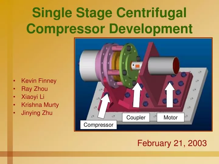
Single Stage Centrifugal Compressor Development. Kevin Finney Ray Zhou Xiaoyi Li Krishna Murty Jinying Zhu. Coupler. Motor. Compressor. February 21, 2003. Single Stage Compressor. Parts currently being manufactured. Impeller (cast aluminum) Diffuser (four axis CNC)

E N D
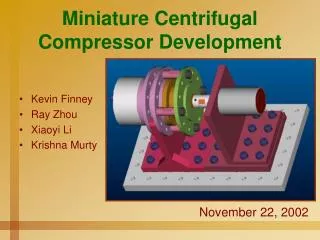
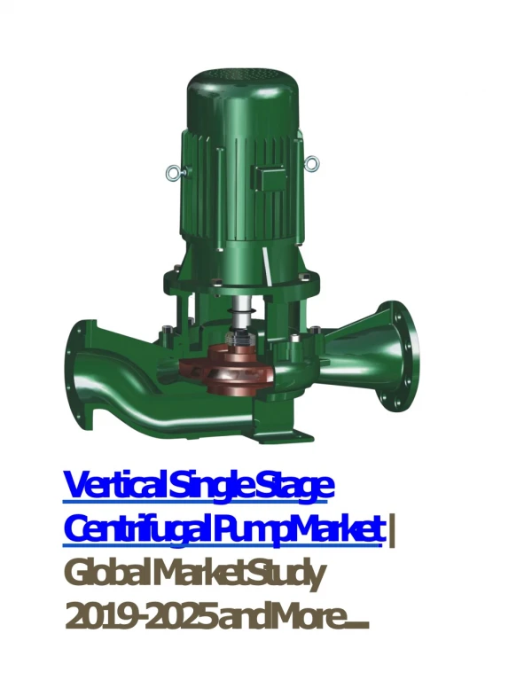
Single Stage Centrifugal Compressor Development • Kevin Finney • Ray Zhou • Xiaoyi Li • Krishna Murty • Jinying Zhu Coupler Motor Compressor February 21, 2003
Single Stage Compressor • Parts currently being manufactured. • Impeller (cast aluminum) • Diffuser (four axis CNC) • Inlet Guide Vane (four axis CNC) • Plastic models have been created showing conceptual idea. • Motor has been tested to 130,000 rpm. • Motor and brackets, as well as cooling jacket for motor seem to work well.
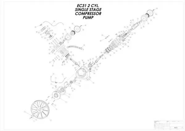
Parts being fabricated… Impeller (cast) Diffuser Inlet Guide Vane
Manufacturing of Parts • Impeller is being cast in Aluminum A356 • Properties of A356 • Used for aircraft and missile components requiring high strength, ductility, and corrosion resistance. • Used for intricate castings such as cylinder blocks, cylinder heads, fan blades, and pneumatic tools • Contains 7% Silicon and traces of Magnesium and Iron. These alloying elements assist in the strength and corrosion properties. • Tensile Strength37ksi • Yield Strength27ksi
Impeller will be machined down to final dimension. Any visible voids will be spot-welded. Surface will be polished to reduce surface roughness. Diffuser and Inlet Guide Vane will be machined out of Aluminum 6061. Scallop height of 0.002”. Tolerance of Diffuser and Inlet Guide Vane will be 0.004”. Finish of Parts Will have three parts of each described above.
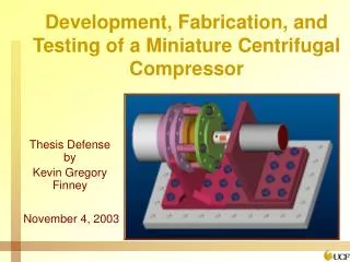
Impeller Inside Coupler Flow Exit Cooling Jacket Diffuser Inside Flow Inlet Motor Inside Motor Lead Wires Common Base
Warm Water Out Motor Shaft Cool Water In
Motor Testing Data • The data stopped at 97,500 rpm due to the inability to measure the speed with the handheld gauge. • With respect to the input voltage, the speed was approximately 130,000 rpm.
Future of Compressor Development • Delivery on the Impellers, Diffusers, and Inlet Guide Vanes will be March 3rd. • Ship Impellers to American Hoffman in West Virginia for balancing. • Assemble compressor and begin tests at low speeds to allow for break-in of bearings. • Test at maximum design speed of 150,000 revolutions per minute and collect data.