Download
1 / 108
1.17k likes | 1.86k Views
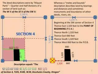
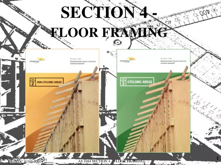
SECTION 4 - FLOOR FRAMING. 4.1 GENERAL. 4.1.1 Scope.

E N D
SECTION 4 -FLOOR FRAMING AS 1684 SECTION 4 – FLOOR FRAMING
4.1 GENERAL 4.1.1 Scope This Section sets out the requirements for the construction of timber-framed floors and, where applicable, decks, verandahs, and the like, and shall be used in conjunction with Span Tables 1 to 6, 33 to 35 and 49 and 50 given in the Supplements. AS 1684 SECTION 4 – FLOOR FRAMING
4.1.2 Materials Any timber species may be used for floor framing, provided it is kept dry; that is, not exposed to weather, well ventilated, not in contact with or close to the ground (see Clause 1.8 and Clause 3.3). When constructing floors that are exposed to the weather (decks, verandahs), attention shall be given to the durability of materials and detailing required to ensure an adequate service life (see Clause 1.8). AS 1684 SECTION 4 – FLOOR FRAMING
4.1.3 Framing configurations Various configurations of bearers and joists may be used to support flooring at either the ground level, or at the first floor level including conventional joists over bearers and joists in line with bearers (low profile floor framing). AS 1684 SECTION 4 – FLOOR FRAMING
4.1.4 Weatherproofing The detailing of wall cladding, flashings and damp-proof course in any construction except for decksshall be such that timber floor frame members will be protected from the weather or ground moisture rising through the substructure. AS 1684 SECTION 4 – FLOOR FRAMING
4.1.5 Shrinkage Where large unseasoned timber members or members with different shrinkage characteristics are used, allowance shall be made for shrinkage. NOTE: Shrinkage associated with the use of seasoned or small section unseasoned bearers and joists (overall depth of floor frame less than 200 mm) is usually of minimal significance to the overall performance of the structure (see Figure F1 in Appendix F). AS 1684 SECTION 4 – FLOOR FRAMING
Appendix F F3 ALLOWANCE FOR SHRINKAGE • Allowance should be made for the effects of shrinkage where any one of the following conditions applies: • (a) Unseasoned members are used. • (b) Materials with different shrinkage characteristics are combined. • (c) Unseasoned timber is used in conjunction with seasoned timber or other non-timber products. • (d) Openings occur in external brick veneer. • (e) In multistorey construction. • (f) In multi-residential timber-framed fire-rated construction. AS 1684 SECTION 4 – FLOOR FRAMING
Appendix F F3 ALLOWANCE FOR SHRINKAGE FIGURE F1 ALLOWANCE FOR SHRINKAGE AS 1684 SECTION 4 – FLOOR FRAMING
Appendix F F3 ALLOWANCE FOR SHRINKAGE FIGURE F1 ALLOWANCE FOR SHRINKAGE AS 1684 SECTION 4 – FLOOR FRAMING
Appendix F F3 ALLOWANCE FOR SHRINKAGE FIGURE F1 ALLOWANCE FOR SHRINKAGE AS 1684 SECTION 4 – FLOOR FRAMING
4.1.5 Cuts, holes and notches in bearers and joists beams and rafters Cuts, holes and notches shall not exceed the sizes, nor be at closer spacing than, given in Figure 4.1. These are also applicable to some Roof Framing Members - See Section 7. Unless otherwise specified, the member size shall not be reduced by any other method to a net section size less than that required to achieve the span requirements. AS 1684 SECTION 4 – FLOOR FRAMING
4.1.5 Cuts, holes and notches in bearers and joists beams and rafters NOTES: 1 Significant imperfections, such as knots,should be regarded as holes with respect to the hole spacing limitations given in Figure 4.1. 2 Engineered timber products may have their own specific limitations (see Clause 1.12). Only one surface at the end of any member shall be notched. AS 1684 SECTION 4 – FLOOR FRAMING
These allowances for cuts, holes and notches are given to allow for installation of plumbing and electrical services and also tie-down. The notching can also be utilised to decrease the overall depth of floor framing. This reduction in floor framing depth may also lead to savings in other materials by reducing the ground to top of floor height and/or reduce the total shrinkage when using unseasoned floor framing .... for example...... AS 1684 SECTION 4 – FLOOR FRAMING
The overall depth of this bearer/joist system is reduced by approx. 90mm which could reduce the possible shrinkage by 6 to 8 mm. If the depth of the bearer is 200mm and the joist 175mm, each of these members can be reduced by ¼ (25%). AS 1684 SECTION 4 – FLOOR FRAMING
FIGURE 4.1 NOTCHES, CUTS AND HOLES IN BEAMS, BEARERS, JOISTS, RAFTERS AS 1684 SECTION 4 – FLOOR FRAMING
FIGURE 4.1 NOTCHES, CUTS AND HOLES IN BEAMS, BEARERS, JOISTS, RAFTERS AS 1684 SECTION 4 – FLOOR FRAMING
NOTE: The details given in Figure 4.1 do not apply to holes required for the provision of tie down bolts at member support positions. These holes may be inserted in addition to the notching limitations at supports. Holes for tie-down bolts away from supports shall be spaced in accordance with Figure 4.1 (e). AS 1684 SECTION 4 – FLOOR FRAMING
4.2BUILDING PRACTICE 4.2.1 Bearers 4.2.1.1 General Where required, bearers shall be levelled, preferably by checking (notching) out the underside over supports. this refers to unseasoned timber where the allowable tolerances of the timber size is + or – 3mm. AS 1684 SECTION 4 – FLOOR FRAMING
4.2.1.1 Bearers General Bearers with minor spring, within the allowable limits, shall have the spring placed upwards to allow for straightening under loading. allowable limits for spring are those given in the stress grading standards such as – AS2082 (hardwood) AS2858 (softwood). Packing of minor deficiencies in depth is permitted, provided the packing is a corrosion-resistant, incompressible material over the full area of support. AS 1684 SECTION 4 – FLOOR FRAMING
4.2.1.1 Bearers General Joints in bearers shall occur only over supports, with adequate bearing for both members. Figure 4.2 shows various connection methods that can be used over supports. All cuts shall be located over a support. The minimum bearing each side of a join shall be 50 mm. …. by the full width of the bearer or equivalent area. AS 1684 SECTION 4 – FLOOR FRAMING
FIGURE 4.2 BEARER SUPPORTS (ALTERNATIVES) AS 1684 SECTION 4 – FLOOR FRAMING
This cut must be over the supporting stump, pier, post etc. 50 mm min. 50 mm min. The minimum bearing each side of a join shall be 50 mm. All cuts shall be located over a support. AS 1684 SECTION 4 – FLOOR FRAMING
This cut must be over the supporting stump, pier, post etc. 50 mm min. Full width of flange may be used for bearing. All cuts shall be located over a support. The minimum bearing each side of a join shall be 50 mm. AS 1684 SECTION 4 – FLOOR FRAMING
4.2.1.1 Bearers General NOTES: Bearers may be planed to within the allowable tolerances of the member specified. Some engineered nailplated products may permit joins to occur other than over supports (seeClause 1.12). AS 1684 SECTION 4 – FLOOR FRAMING
4.2.1.2 Fixing of bearers to supports Bearers shall be fixed to their supporting stumps, posts or columns in such a manner as will give adequate bearing and provide restraint against lateral movement (see Clause 9.7). (Shear Forces) Clause 9.7 states ….“Shear forces (lateral wind forces) are required to be resisted by connections at thebearer and joist levelof the house to prevent ‘sliding’.” AS 1684 SECTION 4 – FLOOR FRAMING
4.2.1.3 Built-up bearers Any of the joining methods shown in AS1684 Figure 4.2 are also suitable for vertically nail laminated bearers. A typical modification of these joining methods for vertical nail laminated bearers is shown at left. The required breadth of larger section bearers may be obtained by vertically nail-laminating thinner sections together (see Clause 2.3). AS 1684 SECTION 4 – FLOOR FRAMING
4.2.1.4 Double bearers (spaced bearers) The required breadth of larger bearers can be obtained by using spaced double bearers. Spacer blocks shall be placed between the bearers and, where relevant, at supports, at the intervals specified in Table 4.1. Spaced bearers are typically used in pole frame construction. AS 1684 SECTION 4 – FLOOR FRAMING
4.2.1.4 Double bearers (spaced bearers) This method is applicable to seasoned and unseasoned timber, however there are no 38 mm or 50 mm bearer sizes given for unseasoned timber in the span tables. Where appropriate, this method can be used instead of vertical nail lamination. AS 1684 SECTION 4 – FLOOR FRAMING
FIGURE 4.3 DOUBLE BEARER AS 1684 SECTION 4 – FLOOR FRAMING
4.2.2 Joists 4.2.2.1 General Joists shall be laid with their top surfaces level to receive flooring. The undersides of joists having minor excesses shall be notched over bearers in order to bring them to the required level. Packing of joists having minor deficiencies in depth may be utilized, provided the packing is fixed and is of corrosion resistant and incompressible material over the full area of contact. AS 1684 SECTION 4 – FLOOR FRAMING
4.2.2.1 General Spacing of joists shall be determined by the span capacity of the flooring (see Section 5). This is a very important point to note, as the span capacity of the strongest 19mm thick end-matched hardwood flooring is 520mm and some pine flooring can be only 390mm. 19mm thick hardwood decking is 500mm and 22mm pine decking is 450mm. AS 1684 SECTION 4 – FLOOR FRAMING
4.2.2.1 General Joists having minor spring (within allowable limits) shall be laid such as to allow for straightening under loading. i.e. spring up allowable limits for spring are those given in the stress grading standards such as – AS2082 (hardwood) AS2858 (softwood). AS 1684 SECTION 4 – FLOOR FRAMING
4.2.2.1 General Regardless of their length, if joists are partially cut over supports to correct bow or spring they shall be deemed to be supported at two points only (single span). Where cuts are used to correct bow or spring, they shall be located centrally over the support, so that each side of the cut section is adequately supported. AS 1684 SECTION 4 – FLOOR FRAMING
4.2.2.1 General Joints in joists shall be as shown in Figure 4.4 and shall be made only over bearers or supports. Joists joined over bearers or supports shall have minimum 30 mm bearing for each joist. Joints in joists that are required to be in line (for example, supporting wall plates or fitted flooring) shall be butted or scarfed, but shall not be lapped. AS 1684 SECTION 4 – FLOOR FRAMING
4.2.2.1 General Note: Lapping joists, irrespective of how much they are lapped or fixed, does not allow the continuous span tables to be used unless specifically engineer designed. AS 1684 SECTION 4 – FLOOR FRAMING
FIGURE 4.4 METHODS OF JOINING JOISTS AS 1684 SECTION 4 – FLOOR FRAMING
The length of the scarf 'S' to be no greater than twice the bearing length Scarf joint. S 30mm min. bearing each side of joint. ALTERNATE SCARF JOINT AS 1684 SECTION 4 – FLOOR FRAMING
4.2.2.2 Location of joists The following apply: (a) Fitted flooring For flooring that abuts wall plates, a pair of joists shall be provided under each wall that is parallel to the direction of the joists. These joists shall be spaced to provide solid bearing and fixing for the bottom wall plate and to project not less than 12 mm to give support for fixing of the flooring (see Figure 5.1). AS 1684 SECTION 4 – FLOOR FRAMING
4.2.2.2 (a) Fitted flooring Joists suitably spaced to provide bearing for bottom plate and flooring. AS 1684 SECTION 4 – FLOOR FRAMING
4.2.2.2 Location of joists (b) Platform flooring Where flooring is continuous under wall plates, joists shall be provided directly under all loadbearing walls parallel to the joists. A single joist only is required under external non-loadbearing walls. Joists are not required under internal non-loadbearing walls except as required to support flooring. AS 1684 SECTION 4 – FLOOR FRAMING
4.2.2.2 (b) Platform flooring Non-loadbearing walls. Single joist only under external non-loadbearing walls. Joists are not required under internal non-loadbearing walls. AS 1684 SECTION 4 – FLOOR FRAMING
4.2.2.3 Deep joists Where the depth of floor joists is equal to or exceeds four times the breadth (deep joists), the joists shall be restrained at their supports with either— (a) a continuous trimming joist provided to the ends of joists above external bearers or wall plates; or (b) solid blocking or herringbone strutting between the outer pairs of joists and between intermediate pairs at not more than 1.8 m centres. AS 1684 SECTION 4 – FLOOR FRAMING
4.2.2.3 Deep joists Trimmers or solid blocking may be 25 mm less in depth than the joists (see Figure 4.5) or other equivalent method for the purpose of ventilation. Trimmers or solid blocking shall be a minimum thickness of 25 mm. AS 1684 SECTION 4 – FLOOR FRAMING
4.2.2.3 Deep joists This restraint is required to stop the floor joist ‘rolling over’ due to lateral loads on the building such as from wind or earthquake. earthquake AS 1684 SECTION 4 – FLOOR FRAMING
4.2.2.3 (a) continuous trimming joist provided to the ends of joists Trimming joist Deep floor joist. Depth (D) equal to or greater than 4 x breadth (B) Lower storey top plate or bearer AS 1684 SECTION 4 – FLOOR FRAMING
NOTE: Where a continuous trimming joist is provided to the ends of joists above external bearers or wall plates, solid blocking or herringbone strutting, at not more than 1.8 m centres, shall also be provided to internal bearers or wall plates. AS 1684 SECTION 4 – FLOOR FRAMING
4.2.2.3 (b) solid blocking or herringbone strutting Solid blocking or herringbone strutting at external and internal supports at not more than 1.8 m centres Deep floor joist. Depth (D) equal to or greater than 4 x breadth (B) Lower storey top plate or bearer 1800 mm max. AS 1684 SECTION 4 – FLOOR FRAMING
4.2.2.3 Deep joists In addition, for deep joists in unseasoned timber where the span exceeds 3.0 m and there is no ceiling installed on the underside of joists, herringbone strutting or solid blocking shall be provided between all joists in evenly spaced rows not exceeding 1800 mm centres. AS 1684 SECTION 4 – FLOOR FRAMING
4.2.2.3 Deep joists Additional blocking or strutting (mid-span) for unseasoned deep joist over 3 m span with no ceiling underneath 1800 mm max. AS 1684 SECTION 4 – FLOOR FRAMING
Because the bottom edge of unseasoned deep floor joist may tend to distort due to normal drying stresses, strutting or blocking is required for unseasoned joist over 3m that do not have a ceiling attached to restrain the bottom edge. Mid-span strutting or blocking is NOT required for seasoned joist. AS 1684 SECTION 4 – FLOOR FRAMING