Download
1 / 8
80 likes | 330 Views
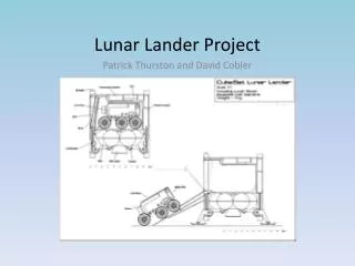
Final Slides Lunar Lander Structure. April 9, 2009 Lunar Descent Phase Group. 1. Basic Frame Design. Drivers in frame mass Total Lunar Lander (LL) mass at lunar touchdown Volume of LL Shape: Conic Frustum Stores all Lunar Lander subsystems while minimizing volume

E N D
Final SlidesLunar Lander Structure April 9, 2009 Lunar Descent Phase Group [Ryan Nelson] [STRC] 1
Basic Frame Design Drivers in frame mass Total Lunar Lander (LL) mass at lunar touchdown Volume of LL Shape: Conic Frustum Stores all Lunar Lander subsystems while minimizing volume All frame components hollow Small leg diameter allows for storage within side supports prior to lunar touchdown Schematic of frame listing components 2
Backup Slides (Frame Design) Thickness of all frame components varies First mode of failure (factor of safety = 1.5) Payload case Cross sectional shape is circular or rectangular for all components 0.5 mm magnesium skin place around Lunar Lander frame Micrometeorite protection Thermal protection 4
Backup Slides (Floor Supports) Support a majority of landing loads Thickness altered until load is supported Hollow Rectangular Cross section Moment of Inertia Bending Stress acting on beam 5
Backup Slides (Side Supports/Legs) First mode of failure is buckling K=0.5 for side supports (both ends fixed) K=2.0 for legs (one end is free to move) Hollowing the rod decreases moment of Inertia and critical load Fcr = 6
Backup Slides (Side Supports/Legs) Compression failure occurs after buckling for both side supports and legs Despite small cross sectional area Compression failure Top, Bottom, and Engine Support rings all designed to have same cross sectional dimensions 7