Download
1 / 38
380 likes | 545 Views
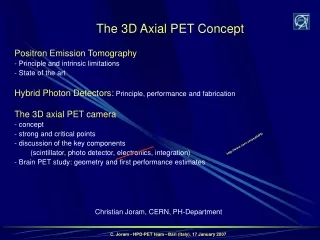
Demonstration of an Axial PET concept for Brain and Small Animal Imaging. Vienna Conference of Instrumentation 2010 Paolo Beltrame CERN - PH/DT. The AX-PET concept The Demonstrator Characterization Simulation and Reconstruction Next steps and future plans. The AX-PET Collaboration.

E N D
Demonstration of an Axial PET concept for Brain and Small Animal Imaging Vienna Conference of Instrumentation 2010 Paolo Beltrame CERN - PH/DT • The AX-PET concept • The Demonstrator • Characterization • Simulation and Reconstruction • Next steps and future plans
The AX-PET Collaboration Istituto Nazionale di Fisica Nucleare Bari(INFN) Ohio State University (OSU) European Organization for Nuclear Research (CERN) University of Michigan • University of Rome La Sapienza(INFN) Instituto de Fisica Corpuscular (IFIC) Paul Scherrer Institute (PSI) Eidgenössische Technische Hochschule (ETH) • P. Beltrame, A. Braem, V. Fanti, C. Joram, T. Schneider, • J. Séguinot, C. Casella, G. Dissertori, L. Djambazov, W. Lustermann, • F. Nessi-Tedaldi, F. Pauss, D. Schinzel, P. Solevi, • J. F. Oliver, M. Rafecas, R. De Leo, E. Nappi, E. Chesi, H. Kagan, A. Rudge, • P. Weilhammer, D. Renker, N. Clinthorne, E. Bolle, S. Stapnes , F. Meddi VCI2010 - P. Beltrame
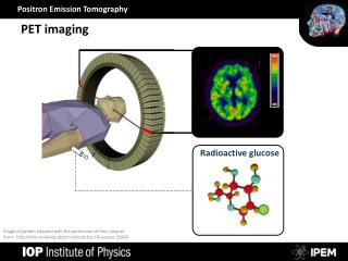
General introduction PET: Positron Emission Tomography metabolic active molecule marked with isotope b+ emitter e+e- annihilation: back to back photons of 511 keV VCI2010 - P. Beltrame
The standard PET L Radial resolution Detection Efficiency dp a • Short, radially oriented crystals • Readout in blocks by PMTs • No Depth of Interaction • (some exceptions) • No Depth of Interaction knowledge • Parallax error • Detection efficiency VCI2010 - P. Beltrame
From PET to AX-PET From short radial oriented, block readout crystals … to long axially oriented, individually readout crystals VCI2010 - P. Beltrame
The concept and the demonstrator VCI2010 - P. Beltrame
The crystal+WLS “grid” scintillation light x wavelength shifted light How to measure the axial coordinate? z MPPC y MPPC • Light transport along the bars and the strips by means of total internal reflection • Light detection • - crystals: energyand x,y-location • - WLS strips: z-position along the crystal Crystal WLS VCI2010 - P. Beltrame
The crystal+WLS “read out” scintillation light x wavelength shifted light How to read the crystals? z MPPC y MPPC • Light detection by • novel photo detectors G-APD = MPPC=SiPM • High PDE: ~50% • Very fast: <1 ns peaking time • Immune to B-field • (used in combination with MRI and CT) Crystal WLS VCI2010 - P. Beltrame
The AX-PET components: LYSO Crystal material: LYSO Manufacturer: Saint-Gobain Dimensions: 3 × 3 × 100 mm3 • Prelude 420TM • Chemical composition: Lu9YSiO25 • Non hygroscopic • Density: 7.1 g/cm3 • Absorption length: 1.2 cm • Peak emission spectrum: 420 nm • Refraction index (420 nm): 1.81 • Light yield: 32 photons / keV • Decay time: 41 ns, single exponential VCI2010 - P. Beltrame
The AX-PET components: WLS WLS material: Polyvinyltoluene + dopant Manufacturer: ELJEN Technology Dimensions: 0.9 × 3 × 40 mm3 • EJ 280 • Shifts blue light into green one • Density: 1.023 g/cm3 • Maximum absorption: 425 nm • Maximum emission: 490 nm • Refraction index: 1.58 • Decay time: 8.5 ns • QE (fluorescent material): 0.86% • Doping: 10x with respect to standard Kapton cable MPPC VCI2010 - P. Beltrame
The AX-PET components: photo detectors MPPC Manufacturer: Hamamatsu Operational voltage: ~70 V Crystal readout • MPPC LYSO: S10362-33-50-C • active area: 3 x 3 mm2 • 3600 pixels of 50 x 50 mm2 • Gain: 5.7 x 10⁵ • Ceramic package 5.9 x 6.6 mm2 WLS readout • MPPC WLS: MPPC-OCTAGON-SMD • custom made • active area: 3.22 x 1.19 mm2 • 1200 pixels of 70 x 70 mm2 • Gain: 4 x 10⁵ • Octagonal plastic package VCI2010 - P. Beltrame
layer 1 6 The Demonstrator • Two identicalmodules. Each module: • 48 LYSO bars (6 layers x 8 crystals) • - 156 WLS strips (6 layers x 26 strips) 2 modules -> 408 channels WLS strips LYSO bars 1.75 mm staggering WLS MPPC LYSO MPPC 7 mm distance between layers Crystals and WLS strips read out on alternate sides to allow maximum packing density Layers optically separated 3.5 mm LYSO pitch 3.2 mm WLS pitch VCI2010 - P. Beltrame
Putting everything together VCI2010 - P. Beltrame
Fully assembled module VCI2010 - P. Beltrame
… with light protection cover and cables VCI2010 - P. Beltrame
Front-End electronics 1 channel (simplified) test SE (crystals only) MPPC Channels above threshold fast OPA486 Analog output: Light per crystal / WLS Bias ‘slow’ S&H VATAGP5 (128 ch.) • Analog readout of crystals and WLS strips • Sequential or sparse (only channels above threshold) • Fast energy sum of all crystals of 1 module • Trigger on 2 x 511 keV deposition in 2 modules VCI2010 - P. Beltrame
chaRacterization VCI2010 - P. Beltrame
Test set up • 22Na source (ø = 250μm; A = ~900 kBq) Single module characterization Two module characterization 2D moving station PMT 2D moving station Module Module 1 Module 2 Tagger Source Source • Module in coincidence with a tagging scintillator • Use of different tagging crystals • Distance between modules = 15 cm VCI2010 - P. Beltrame
Energy calibration Intrinsic Lu radioactivity + Photopeak “self-calibrating” device [511 keV] • Deviation from linearity due to MPPC saturation (3600 pixels), ~5% effect • Parameterization: logarithmic function [303 keV] [202 keV] [63 keV] VCI2010 - P. Beltrame
Energy resolution Individual crystals: < R_FWHM > ~11.6% @511 keV (averaged on all crystals) Sum signal (48 crystals) R_FWHM_Sum~12.25% @511 keV (on the summed distribution) VCI2010 - P. Beltrame
Axial (z) resolution layer 6 1 z coordinate = CofG of hit WLS strips (typically 2-4) z lay6 lay5 lay4 g x y lay2 lay3 lay1 • si[i=1,6] include: • intrinsic spatial resolution • beam spot size on each layer s(d=0) ~0.76 mm FWHM ~1.8 mm (still includes size of source) VCI2010 - P. Beltrame
First coincidence measurements • Photoelectric events only (1 hit crystal per module) • Draw “LOR” (pure geometrical) VCI2010 - P. Beltrame
Estimate of axial resolution Intersection with central plane FWHM = 1.5 mm Resolution still includes size of source. Finite positron range (in water: <range> = 0.6 mm) VCI2010 - P. Beltrame
Simulation and reconstruction VCI2010 - P. Beltrame
Simulation • Geant4: multi-purpose Monte Carlo tool • (optical transport, dedicated geometry) • GATE: PET dedicated MC • (time dependent phenomena, scanner rotation, • source/phantoms...) Energy - ELOW=40 keV, ESUM=[400,600] keV Excellent data/MC agreement VCI2010 - P. Beltrame
Reconstruction • Dedicated reconstruction code, based on MLEM (Maximum Likelihood Expectation Maximization) • Geometrical component of the System Matrix computed using Siddon'sray-tracing technique. In addition, crystal attenuation and penetration effects also taken into account in the System Matrix • Code tested with several Monte Carlo phantoms Monte Carlo data for a cylindrical source: D = 10 mm, h = 10 mm • FOV: 25 x 25 x 25 mm3 • Voxel: 25 x 25 x 25 vox3 • #steps = 6 • Distance = 10 cm 10 mm 10 mm Projections (x, y, z) 3D image VCI2010 - P. Beltrame
Summary + Next steps and future plans VCI2010 - P. Beltrame
Summarizing the AX-PET main features • 3D localization of photons parallax-free • Optimization of spatial resolution (reducing crystal and WLS strip dimensions) and sensitivity(adding layers) can be done independently. • Possibility of identification a significant fraction of Compton interactions (Inter Crystal Scatter). • ICS events can either be discarded (resolution fully maintained) or reconstructed (increased sensitivity). • Scaling in size and in number of layers to match specific needs: brain PET, small animal PET, PEM (mammography), full body PET. • Concept and components are in principle MRI compatible and TOF extendable. VCI2010 - P. Beltrame
What’s next • At CERN • Mount set-up on a horizontal gantry (rotating source + 1 module rotation +/- 60°) • At ETH Zurichin cooperation with Centre for radio-pharmaceutical Science • April 2010 • Tomographic reconstruction of small animal phantoms (FDG) • Optimization of Monte Carlo and reconstruction code • Time scale 1 year • Performance extrapolation (Monte Carlo) to full scanner and specific geometries VCI2010 - P. Beltrame
AX-PET a novel concept for … brain small animals thanks for your attention VCI2010 - P. Beltrame
back-up slides VCI2010 - P. Beltrame
LYSO and WLS VCI2010 - P. Beltrame
Read Out Electronics • Preamplifiers • Fast operational amplifiers • (~1 GHZ gain x bandwidth) • 50 ohm input impedance • ~50 cm away from the modules, • co-axial cables (50 Ω) • Sum signals of one module • Coincidence Trigger • Bias supply (custom designed) • 256 channels (from 0 to 100 V) • AD5535; 32 channel HV DAC • Precision ~10 mV • after individual calibration of all channels • USB interface • Coincidence Trigger • Coincidence of sum of module signals • with the other module • Thresholds set using oscilloscope • e+e- annihilation events • Self Triggering VATA GP5 • Moderate threshold • LYSO intrinsic radioactivity • Low threshold • pedestal measurement • DAQ… VATA GP5 • 128 channel charge integrating amplifier • (64 channel used) • Shaping time ~250 ns • Fast shaper ~40 ns plus discriminators • self triggering • Hit register • sparse mode readout VCI2010 - P. Beltrame
Energy calibration • Fit a double Gaussian distribution • to the sum of the energy depositions of all crystals of one module with mean values: • Ep = photo peak energy • Ep – 63 keV • to take into account the Luthetium Ka escape line at 63 keV Sum of energy depositions in crystals of one module Module 2 • Energy resolution: • 12.34% FWHM (Module 1) • 12.53% FWHM (Module 2) Module 1 • Peak Position: • (511.7 ± 0.6) keV (Module 1) • (511.8 ± 0.6) keV (Module 2) VCI2010 - P. Beltrame
Time performances • First estimate of the time resolution: • measure delay of coincidence wrt Module2 • measurement from the scope [LecroyWaverunner LT584 L 1GHz] MODULE1 LYSO SUM Trigger MODULE2 LYSO SUM Time resolution : σ~800 ps VCI2010 - P. Beltrame