Download
1 / 37
370 likes | 480 Views
NSTX-U. Supported by. NSTX-U 5 Year Plan for Macroscopic Stability. Coll of Wm & Mary Columbia U CompX General Atomics FIU INL Johns Hopkins U LANL LLNL Lodestar MIT Lehigh U Nova Photonics Old Dominion ORNL PPPL Princeton U Purdue U SNL Think Tank, Inc. UC Davis UC Irvine

E N D
NSTX-U Supported by NSTX-U 5 Year Plan for Macroscopic Stability Coll of Wm & Mary Columbia U CompX General Atomics FIU INL Johns Hopkins U LANL LLNL Lodestar MIT Lehigh U Nova Photonics Old Dominion ORNL PPPL Princeton U Purdue U SNL Think Tank, Inc. UC Davis UC Irvine UCLA UCSD U Colorado U Illinois U Maryland U Rochester U Tennessee U Tulsa U Washington U Wisconsin X Science LLC J. Berkery (Columbia University) J.-K. Park, A. Boozer, S.A. Sabbagh, S. Gerhardt, R. Raman, J.M. Bialek, K. Kim, J. Menard for the NSTX Research Team Culham Sci Ctr York U Chubu U Fukui U Hiroshima U Hyogo U Kyoto U Kyushu U Kyushu Tokai U NIFS Niigata U U Tokyo JAEA Inst for Nucl Res, Kiev Ioffe Inst TRINITI Chonbuk Natl U NFRI KAIST POSTECH Seoul Natl U ASIPP CIEMAT FOM Inst DIFFER ENEA, Frascati CEA, Cadarache IPP, Jülich IPP, Garching ASCR, Czech Rep NSTX-U 5 Year Plan Review LSB B318, PPPL May 21-23, 2013
Macroscopic stability group will provide the physics basis for long-pulse sustainment Poloidalsensors (Bp) • Uniqueness of NSTX/NSTX-U: • high β above no-wall limit, high rotation with strong NTV braking • Accomplishments in NSTX: • EF correction; RWM active control • Comparison of kinetic RWM stabilization theory to experiments • NTV physics for magnetic braking • Disruption prediction algorithm and halo current measurements • Midplanecontrol coils • n = 1 – 3 error field correction • Magnetic braking of ωφ by NTV Stabilizer plates Radial sensors (Br) • n = 1 active RWM control with: combined Br and Bp PID control or model-based RWM state-space (RWMSC) active control
Overall objective: establish the physics and control capabilities needed for sustained stability of high performance ST plasmas • Demonstrate 100% non-inductive sustainment at performance that extrapolates to ≥ 1MW/m2 neutron wall loading in FNSF • Access reduced n* and high-b combined with ability to vary q and rotation to dramatically extend ST physics understanding • Thrust 1, Stability: • Understand and advance passive and active feedback control to sustain macroscopic stability at low collisionality • Thrust 2, 3D Fields: • Understand 3D field effects and provide physics basis for optimizing stability through equilibrium profile control by 3D fields • Thrust 3, Disruptions: • Understand disruption dynamics and develop techniques for disruption prediction, avoidance, and mitigation in high-performance ST plasmas
Overall objective: establish the physics and control capabilities needed for sustained stability of high performance ST plasmas • Thrust 1, Stability: • Understand and advance passive and active feedback control to sustain macroscopic stability at low collisionality • Resistive wall mode (RWM) active control • New non-axisymmetric control coils (NCC) and enhanced magnetic sensors • MHD mode stability physics • Thrust 2, 3D Fields: • Understand 3D field effects and provide physics basis for optimizing stability through equilibrium profile control by 3D fields • Thrust 3, Disruptions: • Understand disruption dynamics and develop techniques for disruption prediction, avoidance, and mitigation in high-performance ST plasmas
Dual-component PID (Br + Bp) and model-based RWM state-space (RWMSC) active control will enable long pulse, high β operation Active n = 1 Bp+ BRfeedback control 6 Feedback on • Year 1 of 5 year plan (2014): • Expand/analyze RWMSC for 6 coil control and n>1 physics 140124 140125 140126 140127 bN 4 2 Brphase = 225o 0 Brn = 1 (G) 6 • Years 2 & 3: • Establish Br + Bp active control capability in new machine, use with snowflake divertor 4 2 Brphase = 180o 0 0.0 0.2 0.4 0.6 0.8 1.0 1.2 t (s) Brphase = 0o Br phase = 90o • Examine RWMSC with: • independent actuation of six coils • multi-mode control with n up to 3 • rotational stabilization in the model RWMSC Advantages: potential for use of external coils with less power • Years 4 & 5: • Utilize model-based active control with the new NCC to demonstrate improved global MHD mode stability and very low plasma disruptivity, producing highest-performance, longest-pulse plasmas
NCC will greatly enhance physics studies and control;Enhanced magnetics near divertor will measure multi-modes Partial NCC • Years 4 & 5: • Implement improvements to active feedback of n =1-3 modes via RWMSC control allowed by the partial NCC • Utilize rotation profile control capabilities allowed by the partial NCC to demonstrate reduced disruptivity by actively avoiding global instability boundaries Existing coils (Next talk by Park will concentrate on NCC) Multi-mode n = 1 ideal eigenfunctionfor fiducial plasma Present sensor locations Proposed new sensor locations • Mode diagnosis: • If two modes are near marginal, need to be able to distinguish • Measure increased amplitude near divertor (3D analysis shows >2x increase over present sensors) • Similar results in ITER simulations • Significant toroidal phase change would be measured • Can help constrain the RWMSC mmVALEN
MHD spectroscopy shows improved stability at high bN/li;kinetic RWM stability may be enhanced at low n Resonant Field Amplification (RFA) vs. bN/li 0.1 0.0 -0.1 -0.2 -0.3 -0.4 Theory: RWM γ vs. n and wf • Years 1 - 3: • Investigate the dependence of stability on reduced n through MHD spectroscopy; compare to kinetic stabilization theory • Years 4 & 5: • Utilize rotation control, NCC, and cryo-pump (for reduced n) to change proximity to kinetic resonances for RWM control Decreasing Collisionality unstable mode Growth rate gtw off resonance All NSTX discharges since 2006 on resonance bN 0.0 0.5 1.0 1.5 2.0 Rotation ω/ωexp li • Mode stability directly measured in experiment using MHD spectroscopy • Decreases up to bN/li= 10 then increasesat higher bN/li • Agrees with larger NSTX disruption database
Realizing NSTX-U long-pulse scenarios will require stability of internal MHD modes Low frequency mode activity measured with multi-energy soft X-ray NSTX-U: Combinations of NB sources • Years 2 & 3: • Use new neutral beam and qmin control to determine increment of qmin above rational values to avoid internal modes • Detect internal modes with RWMSC and non-magnetically with ME-SXR • Years 4 & 5: • Examine time-evolution of global mode internalization using newly-installed, additional toroidally-displaced ME-SXR diagnostic • Combine rotation, q, and βN control to demonstrate improved RWM/internal MHD mode stability Coupled saturated 1/1 kink and 2/1 tearing modes grow when qmin -> 1 (steady-state)
Overall objective: establish the physics and control capabilities needed for sustained stability of high performance ST plasmas • Thrust 1, Stability: • Understand and advance passive and active feedback control to sustain macroscopic stability at low collisionality • Thrust 2, 3D Fields: • Understand 3D field effects and provide physics basis for optimizing stability through equilibrium profile control by 3D fields • Error field (EF) correction • Locking and tearing modes with resonant and non-resonant Efs • Tearing mode physics vs. rotation and rotation shear • Neoclassical toroidalviscosity • Thrust 3, Disruptions: • Understand disruption dynamics and develop techniques for disruption prediction, avoidance, and mitigation in high-performance ST plasmas
Correction of intrinsic error fields (EFs) is critical for performance; Resonant and non-resonant EFs affect locking and tearing stability Dynamic error field correction in NSTX • Year 1: • Use IPEC to model EFs • Years 2 & 3: • Assess intrinsic EFs in new machine • Optimize dynamic EF correction, including n>1 and using 6 SPAs and RWMSC • Investigate resonant EF effects on tearing mode onset • Years 4 & 5: • Utilize NCC to understand locking and tearing modes in the presence of resonant and non-resonant EFs • develop predictability for ITER Gain Resonant error field threshold vs. locking density (IPEC) for five devices
NSTX-U will investigate tearing mode physics vs. rotation and rotation shear Low rotation is bad for the NTM threshold • Year 1: • Analyze NSTX TM/NTMs, project to NSTX-U with resistive DCON, MARS-K, M3D-C1 • Years 2 & 3: • Investigate the rotation and rotational shear vs. TM/NTM in NSTX-U, compared with NSTX • Investigate the β limit for TM/NTM onsets with varied rotation and rotation-shear • Years 4 & 5: • Use the partial NCC and the 2nd NBI beam to study TM/NTM dynamics as a function of (βN,vϕ) • develop predictability for ITER Rotation shear may be an even more important parameter Onset bootstrap drive Rotation shear
NSTX-U will investigate neoclassical toroidalviscosity (NTV) at reduced n, whichis important for rotation controland ITER Theoretically, torque can be a strong function of rotation and n • Year 1: • Analyze existing NSTX NTV data on n dependence and offset rotation • Develop/benchmark leading theory/codes • NTVTOK, IPEC, POCA, FORTEC-3D Analytic n=1 braking NSTX 1.5 1.0 0.5 9 0 • Years 2 & 3: • Assess NTV profile and strength at reduced collisionality, and examine the NTV offset rotation at long pulse • Prepare an initial real-time model of NTV profile for use in initial tests of the plasma rotation control system • Years 4 & 5: • Utilize NCC, demonstrate low rotation profile operation (ITER-like) in steady-state with closed-loop rotation control n/nexp POCA NTV calculations for n=2 and n=3 magnetic braking 0.0 0.5 1.0 1.5 2.0 ω/ωexp
Overall objective: establish the physics and control capabilities needed for sustained stability of high performance ST plasmas • Thrust 1, Stability: • Understand and advance passive and active feedback control to sustain macroscopic stability at low collisionality • Thrust 2, 3D Fields: • Understand 3D field effects and provide physics basis for optimizing stability through equilibrium profile control by 3D fields • Thrust 3, Disruptions: • Understand disruption dynamics and develop techniques for disruption prediction, avoidance, and mitigation in high-performance ST plasmas • Prediction and avoidance • Mitigation with MGI • Transient heat loads and halo currents
Disruption prediction by multiple means will enable avoidance via profile or mode control or mitigation by MGI (1) Predictors (Measurements) Shape/position Eq. properties (b, li, Vloop,…) Profiles (p(r), j(r), vf(r),…..) Plasma response (n=0-3, RFA, …) Divertor heat flux General framework & algorithms applicable to ITER Plasma Operations Control Algorithms: Steer Towards Stable Operation Isoflux and vertical position ctl LM, NTM avoidance RWM and dynamic EF control RWMSC (plasma response) Divertor radiation control Disruption Warning System Avoidance Actuators PF coils 2nd NBI: q, vf, p control 3D fields (upgraded + NCC): EF, vf control n=1-3 feedback Divertor gas injection Loss of Control Mitigation Early shutdown Massive Gas Injection EPI (tbp)
Disruption prediction by multiple means will enable avoidance via profile or mode control or mitigation by MGI (2) Predictors Control Algorithms γ contours Kinetic Physics Avoidance Actuators • Evaluate simple physics criteria for global mode marginal stability in real-time Disruption Warning System MHD Spectroscopy q, vf, βN control • Use real-time MHD spectroscopy while varying rotation, qmin, and βNto predict disruptions Resonant Field Amplification (G/G) 1 RWMSC observer Mitigation ITER gas-loading : Injection into private flux region with higher assimilation efficiency? • Compare mismatch between the RWMSC observer and sensor measurements, and disruption occurence 3D fields, feedback
Disruption prediction by multiple means will enable avoidance via profile or mode control or mitigation by MGI (3) • Year 1: • Model neutral gas penetration of SOL • Years 2 & 3: • Commission MGI system • Characterize density assimilation vs. poloidal location • Years 4 & 5: • Utilize EPI system • Trigger the MGI system based on warning of an impending disruption Predictors • Year 1: • Evaluate initial simple physics model for marginal stability based on kinetic stability physics • Years 2 & 3: • Measure plasma stability using MHD spectroscopy vs. key variables and compare to theory • Compare the mismatch between the RWMSC observer model and sensor measurements, and disruption occurrence • Years 4 & 5: • Implement real-time evaluations of: kinetic stability model, MHD spectroscopy, and RWMSC observer disruption prediction for input to profile control algorithms Mitigation
NSTX-U will provide projections of transient heat loads and halo currents for ITER and FNSF New diagnostic: high-speed IR thermography (ORNL) • Year 1: • Examine thermal loading projections for ITER, including assumptions of axisymmetry • Years 2 & 3: • Investigate halo current toroidal asymmetry and loading on the center column, using newly installed center column shunt tiles • Upgrade shunt tile diagnostics for complete coverage of divertor • Study spatial extent and timing of the heat deposition during VDEs • Years 4 & 5: • Assess halo current scalings using the full field and current capabilities • Study 3D and non-axisymmetric effects on the divertorheat loading Halo current diagnostics = Existing = Baseline plan (others incremental) Halo current rotation 300 200 100 0 f 0.410 0.412 0.414 Time [s] ITER high priority item: ITER has vessel resonances at frequencies of rotating halo currents
Summary of NSTX-U 5 year plan for Macroscopic Stability • MS research is establishing the physics understanding and control capabilities needed for sustained stability of high performance ST plasmas • In unexplored ST operational regime: low n, high β, low li, long pulse • NSTX-U will make critical contributions in the areas of: • Advancement of stability physics and control to sustain macroscopic stability at low collisionality • Understanding 3D field effects and providing the physics basis for profile control by 3D fields • Understanding disruption dynamics and developing techniques for disruption prediction, avoidance, and mitigation • MS research in NSTX-U will be greatly enriched, and have significantly greater impact on ITER, by having the NCC coils
NSTX-U macroscopic stability research is directly coupled to ITER through the ITPA • Through the experimental outage, our group: • Maintains contributions to five joint experiments and two working groups • leads the MDC-2 joint experiment / analysis on RWM physics • co-leads the Working Group 7 effort on aspects of active mode control • Communicated NSTX research bi-annually at each ITPA MHD Stability group meeting for many years • Led two elements of the recent ITPA Integrated Plasma Control Working Group study, led by Dr. Joseph Snipes of ITER • also contributed with direct calculations for ITER on RWM and error field control associated with this effort. • NSTX-U stability research plans expand this effort in the coming five year period.
Dual component (BR, Bp) PID and state space control 80 B d 90 p 40 0 0.56 0.58 0.60 0.56 0.58 0.60 t (s) t (s) Active n = 1 Bp+ BRfeedback control Calculation of Br+ Bpcontrol (VALEN) 2.8 6 Feedback on 140124 140125 140126 140127 bN 4 phase = 0o 2.6 Brn = 1 (G) phase = 90o 2 Brphase = 225o 0 2.4 Brn = 1 (G) 6 phase = 180o 4 0.0 0.04 0.08 0.12 2 Brphase = 180o Dt(s) (model) 0 Model validation and predictive capability: VALEN code feedback predictions 0.0 0.2 0.4 0.6 0.8 1.0 1.2 t (s) Brphase = 0o Br phase = 90o RWM State Space Controller 3D wall, ports, mode currents No NBI port With 3D NBI port d B 90 p Measurement Sensor Differences (G) Measurement Controller Controller • Inclusion of 3D mode and wall detail improves control
RWM active control capability increases as partial NCC coils are added Using present midplane RWM coils Partial NCC 1x12 (upper), favorable sensors • Partial 1x12 NCC coil set significantly enhances control • Present RWM coils: active control to bN/bNno-wall = 1.25 • NCC 1x12 coils: active control to bN/bNno-wall= 1.54 NCC upper 1x12 coils Existing RWM coils
RWM active control capability increases further with full NCC NCC 2x12 with favorable sensors, optimal gain NCC 2x6 odd parity, with favorable sensors • Full NCC coil set allows control close to ideal wall limit • NCC 2x6 odd parity coils: active control to bN/bNno-wall = 1.61 • NCC 2x12 coils, optimal sensors: active control to bN/bNno-wall= 1.70 NCC full 2x12 coils Existing RWM coils NCC partial 2x6 coils
Multi-mode theory shows high amplitude near divertor, enhanced magnetics proposed n = 1 mode Multi-mode n = 1 ideal eigenfunctionfor fiducial plasma poloidalangle center column Presentsensor positions Multi-mode physics • Implement in RWMSC • Validate theory predictions with measurements • Found similar results in ITER simulations new sensors toroidal angle outboardmidplane new sensors Present sensor locations Proposed new sensor locations • Global mode diagnosis: measure theoretically increased amplitude in the divertor at high βN • 3D analysis of candidate sensor positions show >2x increase in signal over present sensors • Significant toroidal phase change would be measured • Constrain RWM state space controller mmVALEN code
3D analysis of extended MHD sensors show significant mode amplitude off-midplane, approaching divertor region n = 1 ideal eigenfunctionfor high beta plasma Z(m) • Model characteristics • New 3D model of divertor plate • 3D sensors with finite toroidal extent; n*A of existing sensors • Results summary • Field amplitude increases >2x with new sensors • Perturbed field reversals observed with new sensors • Signals sufficient with plasma shifted off-midplane Present sensor locations BRsensors (nominally normal, Bnorm) Bpsensors (nominally tangential, Btan) q New sensor locations (includes one new location above midplane) Bnorm vs. theta (normalized to present Br sensors) R(m) Zplasma = -10 cm = -5 cm Present sensors = 0 cm Bnorm(normalized) F = 0 deg F = 0 deg q (deg) q (deg)
Stability control improvements significantly reduce unstable RWMs at low li and high bN; improved stability at high bN/li Unstable RWM Stable / controlled RWM Resonant Field Amplification (RFA) vs. bN/li unstable mode • Mode stability directly measured in experiments using MHD spectroscopy • Stability decreases up to bN/li= 10 • Stability increasesat higher bN/li • Presently analysis indicates consistency with kinetic resonance stabilization • Disruption probability reduced by a factor of 3 on controlled experiments • Reached 2 times computed n = 1 no-wall limit of bN/li = 6.7 • Lower probability of unstable RWMs at high bN/li
Internal modes may limit long-pulse scenarios; kinetic RWM stability may be enhanced at low n 1.5 Unstable RWMs 1.0 n = 1 RFA (G/G) 0 .5 0.0 0 1 2 3 n [kHz] ii Theory: RWM γ vs. n and wf Experiments measuring global stability vs. nsupport kinetic RWM stability theory • Coupled m/n = 1/1+2/1 modes grow when qmin approaches 1 0.1 0.0 -0.1 -0.2 -0.3 -0.4 gtw Collisionality • EPM or ELM triggers cause modes to onset at larger qmin. • “triggerless” internal kinks as qmin -> 1 off resonance on resonance 0.0 0.5 1.0 1.5 2.0 ω/ωexp Model validation and predictive capability: MISK code RWM stability calculations Experiment: RFA vsn • Expectations at lower n: off resonance • More stability on resonancealmost no effect off-resonance Various combinations of neutral beam sources on resonance • Mode stability directly measured in experiment using MHD spectroscopy • Decreases with n“on resonance” • Independent of n“off resonance” • NBCD can determine the required increment of qmin above rational values to avoid internal modes
Internal kink/ballooning modesmust be measured via non-magnetic means • Non-magnetic measurement is also important for mode control systems to be used in future devices with high neutron fluence • The RWMSC can determine how incorrect the observer is in reproducing the measured magnetic flux • Can be used as a criterion as input to a disruption warning system. • Multi-energy soft X-ray can measure low frequency mode activity • used to determine mode amplitude and in conjunction with the external magnetic sensors to determine the degree to which the mode is internal
Understanding neoclassical toroidal viscosity (NTV) is crucial for rotation control “Investigate magnetic braking physics to develop toroidal rotation control at low n” R(12-1) • A new δf guiding-center particle code, POCA, was developed to investigate neoclassical transport in perturbed tokamaks. • solves the Fokker-Planck equation with non-axisymmetric magnetic field perturbations Model validation and predictive capability: NTV calculations with multiple codes, comparison to experiments • NTVTOK code: • Shaing theory NTV computation including ion and electron effects • Comparison to experiment of NTV in all collisionality regimes (b) n=3 (a) n=1 1.5 1.0 0.5 1.5 1.0 0.5 2 0 9 0 n/nexp n/nexp POCA NTV calculations for n=2 and n=3 magnetic braking in NSTX Analytic NTV calculations for (a) n=1 and (b) n=3 magnetic braking in NSTX, as a function of collisionality and rotation 0.0 0.5 1.0 1.5 2.0 0.0 0.5 1.0 1.5 2.0 ω/ωexp ω/ωexp
Correction of intrinsic error fields is critical for studies of 3D field physics and for performance Various successful error field correction schemes in NSTX • Dynamic error field correction (green) • sustains βN above the no-wall limit • sustains substantial toroidal rotation • NSTX-U will have a different error field • Identification of error field in first year of operation • measure vacuum fields; revise models • Perform n=1,2 compass scans with 6 independent SPAs. • RWMSC for dynamic error field correction The perturbed n=1 field (IPEC) from intrinsic error fields in NSTX Predictive capability: IPEC model of error fields
Disruption mitigation technologies that will benefit the ITER design are being prepared MGI research will assess gas penetration efficiency by injection at different poloidal locations A novel mitigation technology, an electromagnetic particle injector (EPI), will be used to terminate plasmas Cone for shattering Particulate container projectile Rail gun electrodes • The EPI is capable of delivering: • A large particle inventory • All particles at nearly the same time • Particles tailored to contain multiple elements in different fractions and sizes • Tailored particles fully ionized only in higher current discharges (to control current quench rates) • Well suited for long stand-by mode operation Predictive capability: Modeling using DEGAS-2 is quantifying the gas penetration past the SOL for NSTX-U • NSTX-U can offer new insight by • Reducing the amount of gas • Injecting gas into the private flux and lower x-point regions of divertorto determine if these are more desirable locations for MGI.
Understanding of thermal quench physics and transient heat loadsis critical for projections Example of rapid disruption with high stored energy • Examining assumptions: • How much stored energy? rapid thermal quench Soft X-ray Typically only 15-20% of the stored energy remains in a late flat top disruption in NSTX neutron emission [arb.] • Halo currents are non-axisymmetric, but are heat fluxes? Proposed expansion of the NSTX-U shunt tile diagnostic set 300 200 100 0 f 0.408 0.410 0.412 0.414 Time [s]
Disruptivity studies and warning analysis of NSTX database are being conducted for disruption avoidance in NSTX-U Disruptivity Warning Algorithms • Disruption warning algorithm shows high probability of success • Based on combinations of single threshold based tests bN q* li All discharges since 2006 • Physics results • Low disruptivity at relatively high bN~ 6; bN/bNno-wall(n=1)~ 1.3-1.5 • Consistent with specific disruption control experiments, RFA analysis • Strong disruptivity increase for q* < 2.5 • Strong disruptivity increase for very low rotation • Results • ~ 98% disruptions flagged with at least 10ms warning, ~ 6% false positives • False positive count dominated by near-disruptive events
MS group continues strong collaborations with other devices such as KSTAR, DIII-D, and ITER team KSTAR:equilibrium operating space 2009 –11 (evolution of > 130 discharges) + new results • DIII-D: RFA of ~ 20Hz n = 1 increase to very high levels while βN increases and rotation decreases • Rapidly rotating n = 1 appears (TM?), clamps RFA amplitude New MP2012-04-23-021 session 1 session 2+ ITER: RWM passive growth rates by CarMa and VALEN • Plasmas have passed the predicted “closest approach” to the n = 1 ideal no-wall stability limit: li = 0.7, bN = 2.5
Many important computational codes are used for theory-experiment comparison on NSTX-U
Many important computational codes are used for theory-experiment comparison on NSTX-U
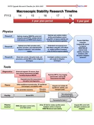
2014-18 Macroscopic Stability Research Timeline FY13 14 15 16 17 18 5 year plan period 5 year plan period 5 year goal Physics Optimize and combine rotation profile and β-feedback control using NCC, to improve stability and for fully non-inductive operation Thrust #1 Optimize shaping, RWM/TM control (n≥1 using the second SPA), validate internal mode physics and RMW kinetic physics Provide FSNF/Pilot projection, Integrate MS control to improve RWM/TM/ELM/ internal mode stability, disruption avoidance, with disruption mitigation protection Understand non-resonant error field effects using NCC, NTV effects vs. rotation profile on transport, utilize 3D field to improve stability Thrust #2 Optimize error field correction (n≥1), dynamic correction, and understand NTV physics in reduced v* and controlled rotation Investigate avoidance scenarios and couple to mitigation techniques Thrust #3 Study halo currents, disruption loads, and precursors, and test MGI or other mitigation techniques Tools Real-time velocity measurement and MSE, toroidallydisplaced ME-SXR Diagnostics Real-time MPTS, X-ray imaging spectrometer, Internal dB measurement from MSE, enhanced magnetic sensors Expanded shunt tile measurements, disruption load diagnostics Theory Utilize equilibrium reconstruction, and transport and stability codes Integrate and validate 3D equilibrium, stability, and transport codes Gas penetration dynamics Disruption simulation Non-axisymmetric Control Coil (NCC), enhanced magnetics, cryopumpfor low v* Facility Second switching power amplifier (SPA), MGI disruption mitigation system Utilize 3D field for rotation (profile) and β-feedback control, to improve RWM/TM/internal mode stability Plasma Control RWM state-space control (n≥1), error field control, snowflakedivertor control Integrate MS control with disruption avoidance and mitigation