Download
1 / 19
190 likes | 344 Views
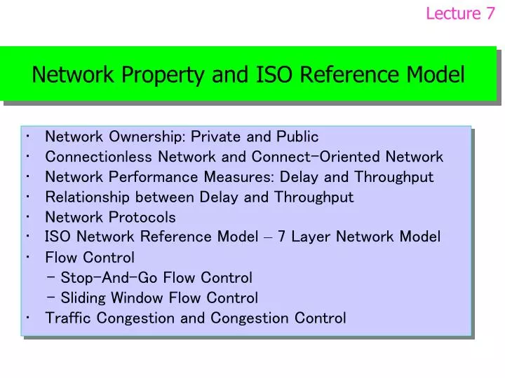
Lecture 7. Network Property and ISO Reference Model. Network Ownership: Private and Public Connectionless Network and Connect-Oriented Network Network Performance Measures: Delay and Throughput Relationship between Delay and Throughput Network Protocols

E N D
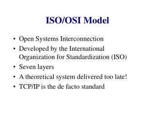
Lecture 7 Network Property and ISO Reference Model • Network Ownership: Private and Public • Connectionless Network and Connect-Oriented Network • Network Performance Measures: Delay and Throughput • Relationship between Delay and Throughput • Network Protocols • ISO Network Reference Model – 7 Layer Network Model • Flow Control - Stop-And-Go Flow Control - Sliding Window Flow Control • Traffic Congestion and Congestion Control
Lecture 7 Network Ownership: Private and Public Private network: owned by individual, single organization or company - Restricted users in an organization or company - Complete, control, installation, management and mantainenance - Often LAN or Multiple LANs in different buildings, different sites linked by lease lines, and with external connects, called intranet. - Can be WAN like bank network need lease lines from phone company Public network: owned by common carrier (e.g., phone company like NTT or KDD) - Operated by common carrier, May be telephone company or other organization - Analogy telephone network, T-/OC- series, Frame Rely, ATM, CATV, etc. - One connection per subscriber * Typical for small corporation on individual * Communicate with another subscriber - Multiple connections per subscriber * Typical for large, multi-site connection * Communicate among multiple sites Ichigaya To Internet T2 T1 T1 T1 Koganei Tama
Lecture 7 Connection-oriented Data Transmission
Lecture 7 Connect-Oriented Network & Connectless Network Connection-Oriented (CO) network - Sender and receiver establish and maintain a connection when they have data to exchange - Sender requests “connection” to receiver, waits for network to form connection, keeps the connection till no longer use, and terminates connection. - Network receives connection request, form path specified destination and inform sender, transfers data across connection, and removes connection when send requests. - The “connection” may not be physically a circuit path * The connection is a virtual path (VP) or virtual channel (VC) for packet switch network Connectionless (CL) network - Sender puts data to network without need to establish a connection similar to postal system - Sender forms packet, places address of intended recipient in packet, put packet to network - Network uses destination address to forward and deliver packet - Characteristics * Packet contains identification of destination * Each packet handled independently * No setup requirement before transmitting data * No cleanup required after sending data Header Payload Trailer Dest Addr Sour Addr
Lecture 7 Comparison and Examples of CO and CL CO - Connection setup overhead - More intelligence in network control - Can reserve bandwidth, reliability, etc. CL - Less overhead - Permits asynchronous use - Allows broadcast and multicast
Lecture 7 Network Performance Measures: Delay and Throughput Delay/Latency - Measure of time for data (bit/packet) to transit network from source to destination - Propagation delay: time to travel across medium - Switching delay: time for network component (hub, bridge, packet switch) to forward data - Access delay: time to get control of medium (CSMA/CD, token) - Queuing delay: time enqueued in packet switches - The former two are nearly constant, the last two are variable Throughput - Measure of rate at which data can be transmitted in network - Capacity, speed and bandwidth of the underlying hardware e.g., 34Kbps modem, 1.5Mbps T1, 6.4Mbps ADSL, 1Gbps gigabit Ethernet - Effective throughput: the rate at which computer can send data less than network capacity because of frame header in each packet and delay Utilization - Ratio of sending data rate to network capacity U Relationship between delay and throughput D = D0 /(1 - U) where D0 is delay when the network is idle and D is total effective delay - Throughput and delay are not independent: T×D=C, data volume on the network - As traffic increase, delays increase. When U1, D∞ and T0, congestion - Network should operates at U<75%, must not operate at U>90% Network Performance Network Throughput & Utilization
Lecture 7 Traffic Congestion and Congestion Control Network congestion - When the input to some link/node reaches/exceeds maximum bandwidth - Packets will queue up at the link/node and some packets will be discarded - Ultimately, network will experience congestion collapse 1 6 30M Bandwidth=100Mbps 50M 2 4 5 Congestion 20M 7 3 Congestion control techniques - Rate control * Limit rate of data transmission * Performed by sending computer * Performed by network - Network Rate control * Monitor incoming traffic * Drop or reject packets over rate * Called traffic shaping Network Congestion Wikipedia, http://en.wikipedia.org/wiki/Network_congestion
Lecture 7 Network Protocols Network Protocol - Agreement about communication * formats of messages (syntax) * meanings of messages (semantics) * rules for data exchange and connection establishment/termination * procedures for handling problems Set of Protocols - A network includes a set of protocols to work together, called protocol suite/family - Each protocol in a protocol suite solves part of communication problem Need for Protocols - Hardware is low level and can’t be directly interacted with computer - Need mechanisms to distinguish among * multiple computers on a network * multiple applications on a computer * multiple copies of a single application - Many problems can occur * bit error, packet lost, packet duplicated, packets in disorder, congestion, etc.
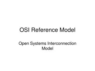
Lecture 7 ISO 7-Layer Network Reference Model - Network protocols are very complex - Protocols are divided into layers • Each layer devoted to one sub-problem • Ease protocols design and implementation • ISO 7-layers reference model • Open System Interaction (OSI) Model • “Layer N” means the Nth layer in ISO model • Not completely same in practical networks Layer 7: Application layer - Application-specific protocols such as FTP and SMTP (email) Layer 6: Presentation layer - Common formats for representation of data Layer 5: Session layer - Management of sessions such as login to a remote computer Layer 4: Transport layer - Reliable delivery of data between computers Layer 3: Network layer - Address assignment and data delivery across a physical network Layer 2: Link layer - Format of data in frame and delivery of frame through network interface Layer 1: Physical layer - Basic network hardware - such as RS-232 or Ethernetencoding OSI model – Wikipedia, http://en.wikipedia.org/wiki/OSI_model
Lecture 7 Layers, Protocol Software and Protocol Stack - One software module per layer; Modules cooperate - Incoming or outgoing data passes from one module to another - Entire modules called protocol stack
Lecture 7 Protocol Layering Principle Two constraints: - The software for each layer depends only on the services of the software provided by lower layers - The software at layer n at the destination receives exactly the same protocol message sent by layer n at the sender These constraints mean that protocols can be tested independently and can be replaced within a protocol stack
Lecture 7 Layers and Packet Headers Each layer - Adds its header to outgoing packet and - Removes header from incoming packet Headers are nested at the front as the message traverses the network Header, here, may include trailer
Lecture 7 Layers, Headers and Data Encapsulation Anim
Lecture 7 Protocol Techniques • For bit corruption: parity, LRC, checksum, CRC • For out-of-order delivery: adding sequence numbers to packets • For duplicated packets: using the sequence numbers • For lost packets: sending acknowledge (ACK) information and retransmission • For reply delay (excessive delay): unique message ID • For data overrun: flow control * Stop-and-go flow control * Sliding window flow control out-of-order: P2P3 duplicated: P5P5 lost packet: P4 P5P4P3P2P1 P5P5P2P3P1 network Receiver Sender Rate Ds in sending Rate Dr receiver can process Data overrun if Ds > Dr Network throughput Dn (> Ds)
Lecture 7 Connection-oriented Data Transmission
Lecture 7 Stop-And-Go Flow Control • Allow sender sends one packet each time and waits • Sending side * Transmits one packet * Waits for acknowledgement from receiver • Receiving side * Receives and consumes packet * Transmits acknowledgement to sender • Inefficient * No data sending in waiting time Anim Flow Control -Wikipedia, http://en.wikipedia.org/wiki/Flow_control_(data) time time
Lecture 7 Sliding Window Flow Control • Allows sender to transmit multiple packets before receiving an acknowledgment • Number of packets that can be sent is defined by the protocol and called the window • Window size is determined by the empty buffer in receiver • Receiver tells how many packets can be sent • Sender transmits a number of packets, specified by available window (buffer) size • Receiver sends acknowledgements as packets arrive Anim
Lecture 7 Comparison of Flow Control • Sliding widow can send data much fast than stop-and-go L Routing table of switch 2 L • For stop-and-go, each packet takes 2L time to deliver where L is the latency, or network delivery time. • Sliding window can improve by number of packets in window: Tw = Tg * W Tw is sliding window throughput Tg is stop-and-go throughput • Transmission time also limited by network transmission rate: Tw = min(B, Tg * W) B is maximum network bandwidth
Exercise 7 1. Explain what are the connection-oriented communication and the connectionless communication. Give some examples for each of the above two types of communications. 2. Describe concepts of delay, throughput, bit corruption (error), disordered packet, duplicate packet, lost packet, flow control and network congestion, respectively. 3. Professionals sometimes refer to a “knee” in the delay curve. To understand what they mean, plot the effective delay for values of utilization between 0 and 0.95. Explain why utilization of a network should not approach to 1. 4. Match the following to one of the ISO 7 layers: a. Route determination. b. Flow control. c. Provides reliable end-to-end transmission of entire message. d. Reassembly of data packets into a message. e. Provides format and code conversion services. f. Provides user services such as electronic mail and file transfer. g. Provides verification of login and logout. h. Mechanical, electrical, and functional interface. 5. Why does a stop-and-go protocol have especially low throughput over a satellite channel that operates at two megabits per second. How to improve throughput using different flow control method?