Download
1 / 27
2.43k likes | 8.05k Views
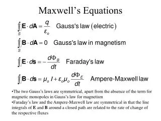
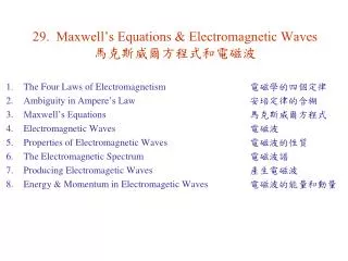
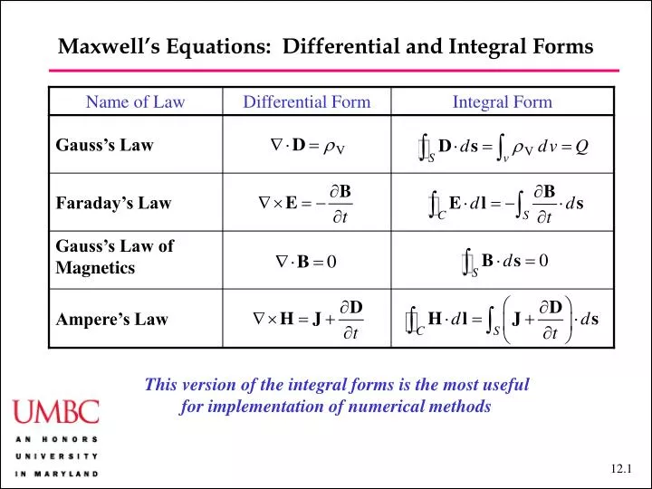
Maxwell’s Equations: Differential and Integral Forms. Name of Law. Differential Form. Integral Form. Gauss’s Law. Faraday’s Law. Gauss’s Law of Magnetics. Ampere’s Law. This version of the integral forms is the most useful for implementation of numerical methods.

E N D
Maxwell’s Equations: Differential and Integral Forms Name of Law Differential Form Integral Form Gauss’s Law Faraday’s Law Gauss’s Law of Magnetics Ampere’s Law This version of the integral forms is the most useful for implementation of numerical methods
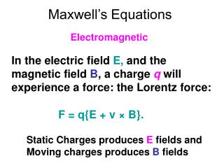
Maxwell’s Equations: Alternative Integral Forms • Faraday’s Law: • F = = magnetic flux • Ampere’s Law: • Ic = conduction current; Id = displacement current • This version of the integral forms • has historical and conceptual importance • is the basis for understanding motors and generators
Faraday’s Law • Electromotive Force: • When a changing magnetic flux passes through a wire loop, it induces a loop voltage VEMF, which is called the electromotive force. • There are two possible sources of change: • The magnetic flux density varies in time, leading to a transformer EMF, • The loop area normal to the flux density varies in time, leading to a motional EMF, • We have Ulaby Figure 6-1
Faraday’s Law ds –dl dl q udt • Electromotive Force: • When the loop has N turns, the effect of the induced EMF is multiplied N times, so we have: Ulaby 2001
Faraday’s Law • Lenz’s Law: • The current in a loop is always in such a direction as to oppose the change of the magnetic fluxF(t) • This law allows us to rapidly determine the direction of the current that is induced by an EMF Ulaby 2001
Tech Brief 12: EMF Sensors EMF Sensors Generate an induced voltage in response to an external stimulus Piezoelectric transducers Certain crystals, such as quartz, become electrically polarized when subjected to mechanical pressure, thereby exhibiting a voltage difference. Under no applied pressure, the polar domains are randomly oriented, but under compressive or tensile stress, the domains align along a principal axis of the crystal. Compression and stretching generate opposite voltages. Discovered in 1880 by Curie brothers. In 1881, Lippman predicted converse property (that electrical stimulus would change the shape of the crystal).
Tech Brief 12: EMF Sensors Piezoelectric transducers Used in microphones, loudspeakers, positioning sensors for scanning tunneling microscopes (can measure deformations as small as nanometers), accelerometers (can measure from 10-4g to 100g), spark generators, clocks and electronic circuits (precision oscillators), medical ultrasound transducers, and numerous other applications
Tech Brief 12: EMF Sensors Faraday Magnetic Flux Sensor According to Faraday’s law, the emf voltage induced across the terminals of a conducting loop is directly proportional to the rate of change of magnetic flux passing through the loop. In the configuration below, Vemf and its derivative directly indicate the velocity and acceleration of the loop.
Tech Brief 12: EMF Sensors Thermocouple Seebeck discovered in 1821 that a junction of two conducting materials will generate a thermally induced emf (called the Seebeck potential) when heated. Becquerel in 1826 used this concept to measure an unknown temperature by relative to a cold reference junction. Traditionally, the cold reference is an ice bath, but in modern thermocouples, an electric circuit generates the reference potential.
Faraday’s Law • Transformers: • These are used to transform voltages, currents, and hence impedances. • In practice, they are made by winding current loops with different numbers of turns around a common magnetic core, which fixes the magnetic flux F. • NOTE: The direction of thewinding determines the polarity of the output. Ulaby Figure 6-5
Faraday’s Law • Transformers: • Voltage Transformation: • In the primary: The oscillating voltage creates an oscillating flux, foundby integrating • In the secondary: • We conclude Ulaby Figure 6-5
Faraday’s Law • Motors and Generators: • Current Transformation: • In an ideal transformer, the power is conserved, so we have P1 = P2.Since P1 = I1V1 and P2 = I2V2, we have • Impedance Transformation: • Ouput resistance, RL = V2/I2 • Equivalent input resistance, Rin = V1/I1 • We conclude Ulaby Figure 6-5
Magnetic Forces • Motors and Generators • We previously discussed motors and generatorsas an application of magnetostatics. That ispossible because the magnetic field is fixedand the currents are moving, so that VEMFis purely motional. • We can instead directly use Faraday’s law! Ulaby Figure 6-11
Magnetic Forces • Motors and Generators • We can instead directly use Faraday’s law! • We first calculate the magnetic flux • We thus find • which is the same result that is obtained from the motional EMF Ulaby Figure 6-12
Displacement Current • … or Maxwell’s great insight! • Original (static) version of Ampere’s law: • This version of Ampere’s law is inconsistent! Why? • Different surfaces attached to same closed curve C yield different results!— Compare • Maxwell assumed that adding to Ampere’s law wouldfix things • …and all experimentalevidence indicates that ithas. C Modified from Ulaby Figure 6-12
Displacement Current Example: Current flow onto a parallel plate capacitor Question: During a time interval t, a steady current Ic flows onto a parallel plate capacitor with area A, separation d, and dielectric constant e, show that the displacement current Id equals the conduction current. Answer: The charge that accumulates on the upper plate of the capacitor is given by where t0 is the initial time at which current starts to flow.Neglecting fringing fields, we have We conclude Ic D Ic
Charge-Current Continuity • Charge conservation • Charge cannot be created or destroyed!
Charge-Current Continuity material relation time • Current Dissipation in Conductors • In real conductors with finite conductivity, excess charge dissipates in a finite time. Using the relations • A good conductor — copper: • A good insulator — mica:
Electromagnetic Potentials • Dynamic Potentials • As before: • From Faraday’s law: • Hence, we must have
Electromagnetic Potentials • Retarded Potentials • In the static case • In the dynamic case, we must take into account the finite time delay: • For the vector potential, we have
Phasor Fields • Time Harmonic Potentials • The building blocks for understanding dynamical systems are sinusoidally varying signals (phasors). • In a linear system, any time variation can be found by adding up the phasors • Maxwell’s equations are linear, assuming linear material relations • We thus write • For the retarded charge density, we have NOTE: In this section of his book, Ulaby uses k and the designation wavenumber, instead ofband the designation phase constant.
Phasor Fields • Time Harmonic Potentials • For the voltage field, we have • which implies
Phasor Fields • Time Harmonic Potentials • For the vector potential and current density fields, we have similarly • which imply
Phasor Fields • Electric and Magnetic Fields— in a non-conducting medium (J = 0) • From the definition of the vector potential, we have • From Ampere’s law, we have • From Faraday’s law, we have
Phasor Fields Field Amplitudes and Dispersion Relations: Ulaby Example 6-8 Question: In a nonconducting medium with e = 16e0 and m = m0, the electric field intensity is given by Determine the associated magnetic field intensity H and the value of k. Answer: We have so that From Faraday’s law: From Ampere’s law:
Phasor Fields Field Amplitudes and Dispersion Relations: Ulaby Example 6-8 Answer (continued): Equating the two expressions for we obtain the dispersion relation This is the same dispersion relation that we found with transmission lines! This is no coincidence!! Explicitly, we have We now find for the magnetic field
Assignment • Reading: Ulaby, Chapter 7 • Problem Set 6: Some notes. • There are 6 problems. As always, YOU MUST SHOW YOUR WORK TO GET FULL CREDIT! • All problems come from Ulaby. • Please watch significant digits. • Get started early!