Download
1 / 41
430 likes | 714 Views
Pressure gauges Compressors Oil separators Condensers Liquid receiver Liquid indicator Evaporators. Expansion valves High pressure cut-out Low pressure cut- in/cut-out Oil pressure cut-out Room temperature control Solenoid valves Drier. System components. Pressure gauges.

E N D
Pressure gauges Compressors Oil separators Condensers Liquid receiver Liquid indicator Evaporators Expansion valves High pressure cut-out Low pressure cut- in/cut-out Oil pressure cut-out Room temperature control Solenoid valves Drier System components
Pressure gauges • The pressure gauge on the compressor suction and discharge shows the gas pressure and also has marked on it the relative condensing temperature. It helps to check correct pressure-temperature relationships for refrigerants. Pressure gauge in the lub oil line is normally of differential type.
Compressors • Refrigeration compressors are usually reciprocating type for marine refrigeration. It may be of the rotary screw displacement type or of the scroll type.
Reciprocating compressors • Reciprocating compressors for systems cooling domestic store rooms are usually of the vertical in-line type. The larger reciprocating compressors have their cylinders arranged in either V or W formation with 4,6, 8, 12 or even 16 cylinders. Compressor speeds have been increased considerably over the years from 500 rev/min to the high speed of 1500 to 2000 rev/min.
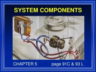
HEAD CRANKCASE PRESSURE EQUALIZING TUBE HEAD GASKET PISTON SPINNER TUBE ASSEMBLY VALVE PLATE GASKET VALVE PLATE WRIST PIN CONNECTING ROD RINGS OIL PRESSURE REGULATOR MAIN BEARINGS OIL PUMP ASSEMBLY OIL PICKUP TUBE & SCREEN ROTOR OIL RETURN CHECK VALVE STATOR OIL DRAIN
V-belt drive • Compressors are usually driven by V-belts. Most are driven at less speed than the motor speed. Pulleys must be in perfect alignment and the pulley shafts (compressor and motor) must be parallel to each other.
Each crank of the crankshaft for the compressor shown carries three bottom ends. The aluminium alloy pistons operate in cast iron liners, which are honed internally. Piston rings may be of plain cast iron but special rings having phosphor-bronze inserts are sometimes fitted. These assist when running in. Connecting rods are H section steel forgings with white metal lined steel top end bushes. The crankcase and cylinders comprise a one-piece iron casting. Main bearings are white metal lined steel shells.
Gas from the evaporator passes through a strainer housed in the suction connection of the machine. This is lined with felt to trap scale and impurities scoured from the system by the refrigerant particularly during the running-in period. Freons tend to clean the circuit but the impurities will cause problems unless removed by strainers. Any oil returning with the refrigerant drains to the crankcase through holes in the diaphragm plate.
Suction and Discharge Valve • There is a valve plate under cylinder head with plate type of suction and discharge valve located in it. Large diameter and very small lifts of plates offer the least resistance to the flow of refrigerant gas. Heavy springs on the discharge valve cage permit a greater valve lift to protect compressor in case of severe liquid refrigerant or oil pumping.
Lubrication • Oil is supplied to the bearings and crankshaft seal by means of a gear pump driven from the crankshaft. Oil pressure is about 2 bar above crankcase pressure and the differential oil pressure gauge is necessary to compare oil pressure with that of the gas in the crankcase. There is a relief valve in the oil system set to about 2.5 bar above crankcase pressure. Protection against oil failure is provided by a differential oil pressure switch.
Crankcase heaters • A certain amount of refrigerant will always be dissolved in the lubricating oil. However, large amounts of refrigerant in the oil are undesirable. Excessive dilution can result in inadequate lubrication. In addition, during compressor start-up, the lowering of the crankcase pressure will cause oil foaming due to the vaporization of the refrigerant. In severe cases, this can disrupt lubrication and can cause carryover of the liquid refrigerant and oil into the cylinder. Since marine systems typically operate on the pump-down cycle, the low crankcase pressure at shutdown limits refrigerant absorption by the oil. Crankcase heaters which come on automatically during the compressor off cycle are used to keep the oil warm and reduce refrigerant absorption.
Shaft seal • A mechanical seal is fitted around the crankshaft at the drive end of the crankcase. This prevents leakage of oil and refrigerant from the crankcase. All seals use two rubbing surfaces. One surface turns with the crankshaft and is sealed to the shaft with an O-ring of synthetic material. The other surface is stationary and mounted on the housing with gasket. The rubbing surfaces can be hardened steel and bronze or ceramic and carbon. The mechanical seal is lubricated from the compressor system.
Unloader mechanism • The most common method of varying the capacity of multi-cylinder compressors is to vary the number of active cylinders by holding the suction valves open. The capacity control system unloads cylinders (i.e., cuts cylinders out of operation) in response to decreases in refrigeration load based on suction pressure.
A bellows device, actuated by suction pressure can serve to cut out one or more cylinders. Under high loads (high suction pressures) none of the suction valves are held open, and all the cylinders are in operation. As the load decreases (and the suction pressure falls off), the cylinders are cut out in sequence. If the suction pressure continues to fall off, the compressor will stop on the low pressure switch. Compressor lubricating oil is used to operate the valve lifting mechanism. Since oil pressure is required to load the cylinder, the compressor will start with all controlled cylinders unloaded, thus reducing the starting load on the compressor motor.
Oil separators • Oil separators may be fitted in hot gas discharge lines from the compressor. It is a closed vessel fitted with a series of baffles or a knitted wire mesh through which the oil-laden vapour passes. The reduction in velocity of the vapour as it enters the larger area of the separator allows the oil particles, which have greater momentum, to impinge on the baffles. The oil then drains by gravity to the bottom of the vessel where a float valve controls flow to the compressor crankcase.
Manual Valves • Manual valves are installed at various locations in the refrigeration system to facilitate system operation, to isolate components for maintenance and for other purposes. Most of the valves used in refrigeration systems are of the packed valve type. They are of the backseating type. When in the open position, the valve is backseated to minimize the possibility of leakage.
Condensers • Most marine refrigeration condensers are of the water-cooled, multipass, shell-and-tube type. Seawater is circulated through the tubes, and the hot gas from the compressor discharge is admitted to the shell and condenses on the outer surfaces of the tubes. The condenser is typically constructed of a steel shell, copper-nickel tubes and tube plates, and bronze waterheads. Gas inlet, liquid outlet, purge, and water regulating valve control connections are provided.
Liquid Receiver • The receiver collects the liquid refrigerant draining from the condenser. It consists of a steel shell with steel dished heads welded on each end. Sight glasses or a liquid level indicator is installed to permit determination of the amount of liquid refrigerant in the receiver. The receiver will typically have sufficient capacity to hold the entire system refrigerant charge and will retain a small liquid level during full load operation. High levels indicate overcharge and low levels indicate undercharge. • Sometimes bottom part of condenser serves as the liquid receiver
Liquid Indicators (Sight Glasses) • Liquid indicators or sight glasses are commonly installed in the liquid line to indicate a proper refrigerant charge. Bubbles appearing in the liquid stream are an indication of a shortage of refrigerant. Some indicators also include a moisture indicator. A portion of the indicator will change color based on the relative moisture content of the refrigerant.
Refrigerant drier • Shell is filled with a desiccant such as activated alumina or silica gel which absorbs moisture and also acts as a filter. Even small amounts of moisture can cause problems such as frozen thermostatic expansion valves, so it is important to remove sufficient moisture to prevent the release of water in the low pressure portions of the system.
Evaporators • Marine evaporators are usually forced convection evaporators. They are in common use in ship’s provision refrigeration and air conditioning systems. The units consist of a cooling coil with finned tubes, a motor-driven fan, and drain pan, all enclosed in a sheet metal casing. Units designed for sub-zero temperature applications are usually fitted with an electric resistance defrost system.
Expansion device • The basic functions of an expansion device used in refrigeration systems are to: • Reduce pressure from condenser pressure to evaporator pressure, and • Regulate the refrigerant flow from the high-pressure liquid line into the evaporator at a rate equal to the evaporation rate in the evaporator • Under ideal conditions, the mass flow rate of refrigerant in the system should be proportional to the cooling load. It is desirable that liquid refrigerant should not enter the compressor. In such a case, the mass flow rate has to be controlled in such a manner that only superheated vapour leaves the evaporator.
Thermostatic Expansion Valve • While there are a number of devices available to control the flow of refrigerant to the evaporator, such as the capillary tube, the float valve, and the constant-pressure expansion valve, the thermostatic expansion valve is the device most commonly found in marine systems. The thermostatic expansion valve responds to the evaporator temperature and pressure and maintains a constant superheat at the outlet of the evaporator. As refrigerant is fed to the evaporator, the liquid boils off into a vapour. By the time the refrigerant gas reaches the end of the evaporator, it is superheated. Feeding more refrigerant to the evaporator will lower the superheat temperature, while feeding less refrigerant will raise the superheat temperature.
This consists of a feeler bulb that is attached to the evaporator exit tube so that it senses the temperature at the exit of evaporator. The feeler bulb is connected to the top of the bellows by a capillary tube. The feeler bulb and the narrow tube contain some fluid that is called power fluid. system. To ensure the correct operation of the valve, the bulb must be securely clamped to the evaporator outlet line.
Pb - Bulb pressure on the upper side of the diaphragm, tending to open the valve, where Pb is the saturation pressure of the refrigerant in the bulb, corresponding to the temperature of the gas at the evaporator outlet. • Po - Evaporator pressure on the lower side of the diaphragm, tending to close the valve, where Po is the saturation pressure of the refrigerant at the evaporator inlet, and Δp is the pressure drop between the evaporator inlet and outlet. • Ps - Pressure exerted by the regulating spring, tending to close the valve. The spring tension, set by the regulating spindle, controls the degree of superheat; a typical superheat value is 4°C to 6°C.
At any constant operating condition, these forces are balanced and Pb = Po + Ps • If the superheat starts to rise, the bulb pressure increases, Pb > Po +Ps and the valve is moved in the opening direction, admitting more liquid and restoring the constant operating condition. • If the superheat falls, Pb < Po + Ps and the valve is moved to the closing position, reducing the supply of liquid. • In practice, to achieve the desired degree of superheat at the evaporator outlet, dry expansion evaporators require up to 20 per cent of their cooling surfaces to be available to superheat the gas, the precise area varying with demand.
TEV with external equalizing connection • There is an appreciable pressure drop in the large evaporators. Additional control is introduced by incorporating a pressure equalising connection. This connection eliminates further increase in the superheat temperature to compensate for the reduction in pressure, and so allows an increase in the effective area of the evaporator.
Back pressure valve in vegetable room • If the evaporator in vegetable room is kept at common pressure of meat room and fish room, then ice formation will take place in this evaporator also. This ice will be formed from the moisture of fruits and vegetables stored in the room and they will become desiccated.
The bellows pressure area and the valve area are equal. The adjustment spring and the evaporator pressure change can operate the valve motion. The valve has a gauge opening to check pressure of the evaporator. For R22 system, this pressure may be 4 bar gauge.
Solenoid valve • The solenoid valve is thermostat controlled valve which provides automatic opening of and closing of liquid line to the evaporator. When the coil (3) is energised, the pilot orifice (4) is opened and the diaphragm (1) moves into open position (vice versa when coil is de-energised).
Thermostats • Thermostats are temperature-controlled electric switches. It is used to control the temperature in a refrigerated space by ‘opening and closing’ a solenoid valve in the liquid line. • Three types of element are used to sense and relay temperature changes to the electrical contacts. • A fluid-filled bulb connected through a capillary to a bellows. • A thermistor • A bi-metal element
High Pressure Cut-out • There are a number of faults which cause high discharge pressure, including loss of condenser cooling, air in the system and overcharge. • In the event of overpressure on the condenser side of the compressor the high pressure cut-out will cause the compressor to shut down. The device is re-set by hand.
The bellows in the cut-out is connected by a small bore pipe between the compressor discharge and the condenser. The bellows tends to be expanded by the pressure and this movement is opposed by the spring. The adjustment screw is used to set the spring pressure. During normal system operation, the switch arm is held up by the switch arm catch and holds the electrical contact in place. Excessive pressure expands the bellows and moves the switch arm catch around its pivot. The upper end slips to the right of the step and releases the switch arm so breaking the electrical contact and causing the compressor to cut-out. The machine cannot be restarted until the trouble has been remedied and the switch re-set by hand.
Low pressure controller • The low pressure control stops the compressor when low suction pressure indicates closure of all cold compartment solenoids. When the pressure in the compressor suction rises again due to one or more solenoids opening, the low pressure control restarts the compressor.
The controller is operated through a bellow which monitors pressure in the compressor suction. A pressure differential between cut out and cut in settings is necessary to avoid hunting. The push pin operates the switch through a contact which is flipped open or closed through a coiled spring plate. With the contacts open the spring is coiled as shown. Outward movement of the pin compresses the spring and this then flips the contact to close the compressor starting circuit.
Oil pressure safety cut-out • This is used to protect against too low oil pressure in forced lubrication systems. It is a differential control, using two connections. One side responds to the suction pressure of compressor and the other responds to the oil pressure. If the differential oil pressure fails, or falls below a minimum value, the control stops the compressor after a certain time delay.