Download
1 / 15
150 likes | 364 Views
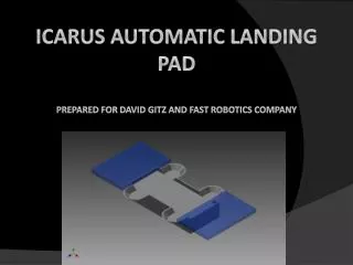
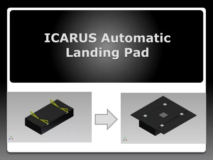
ICARUS Automatic Landing Pad. Team Members. Cory Fulkerson (Project Manager) - Mechanical Engineer John Graham - Computer Engineer Clayton Hooks - Electrical Engineer O’Raphael Okoro - Electrical Engineer Tyler Wilson - Mechanical Engineer. ICARUS Overview.

E N D
Team Members Cory Fulkerson (Project Manager) - Mechanical Engineer John Graham - Computer Engineer Clayton Hooks - Electrical Engineer O’RaphaelOkoro - Electrical Engineer Tyler Wilson - Mechanical Engineer
ICARUS Overview Integrated Complex Advanced Robotic Unmanned System Autonomous Flying Helicopter Co-axial, tilt-capable, quad-rotor vehicle More maneuverable and efficient vehicle than comparable quad rotor helicopters
Reason for ALP The ICARUS Automatic Landing Pad (ALP) will provide a secondary recharge opportunity for the ICARUS vehicle when out in the field during missions which will extend the range of the vehicle as well as increase mission duration.
ALP Requirements Must be robust and lightweight to be field transportable as well as waterproof to protect the electrical components within. Must Effectively communicate with the vehicle to guide it to the pad and be fully autonomous. Must have onboard energy storage and be capable of recharging the vehicle after it has landed in a timely manner. Must recharge itself through solar panels in order to repeat the process.
Current State of Project Electrical systems Software systems Mechanical systems
Electrical Systems Completion Status: • Energy collection subsystem • PV panel received 9-9-11 • Battery, PVCC in shipping • Offline charge facility fabbed/tested 9-1-11 • Energy delivery subsystem • PSCA completed, inductor spec error for PSCA/VSCA found • Converter operates, but inductor is driven into saturation at high output currents; losses high. • Specifications revised, new parts received 9-9-11 • VSCA completed sans inductor, trimpots • Replacement parts received 9-9-11 • Cell equalizer tested 8-12-11 • Load tester • Resistance elements for VSCA/PSCA fabbed 8-13-11 • Tester assembled sans harness/meters 8-15-11
Control system hardware • Control system assembly • CSA demo boards last tested 8-5-11, • Populations moved to mainboard, tested 9-8-11 • Current GPIO uCcode is manual demo only; no interface • Camera interface not tested; camera ordered 9-6-11 • Landing illuminator • LIA converter fabbed, tested 7-27-11 • OPTEK LED lamps tested 7-26-11 • experimentally determined • experimentally determined • NIR lamps etched, LED’s in shipment
Tasks to complete for Electrical Systems • Energy collection subsystem • Assemble PV harness and test basic functionality • Experimentally verify prior estimates of loss parameters • Energy delivery subsystem • PSCA • Replace inductor • Test and evaluate efficiency • Attempt to determine actual switch loss figures to determine necessity of heat sinking • VSCA • Populate inductor, trimpots • Test/troubleshoot and evaluate efficiency • Attempt to determine actual switch loss figures to determine necessity of heat sinking • Program CTuC and verify using load tester • Load tester • Assemble metering harness for PSCA/VSCA eval
Control system hardware • Control system assembly • On camera arrival, fab harness, verify connectivity • If time permits, OPTEK vs NIR response can be evaluated • Landing illuminator • NIR lamps to be fabbed • Experimentally determine for NIR lamps
Software Completion Status: • Serial I/O functions • Create Functions for I/O use 7-SEP-11 • Main Function • Created Flow structure for basic Data input and flow7-SEP-11 • Created function for input data analysis from Com Ports • Completed 7-SEP-11
Tasks to complete for Software • Main Function • Test overall functionality with hardware • Continue debugging for different input scenarios • Create functionality for multiple ports opened • Create functionality for sorting data from unknown origin • Sub-Function Construction • Serial access Functions • Determine sampling rate needed for effective power usage/functionality ratio • Test with hardware, continue debugging • Radio out/in communication Functions • Write and test radio functions • Test/troubleshoot
Mechanical Systems Completion Status: • CAD Drawings Created Using Autodesk Inventor. • 3D part files completed. • Assembly Files completed. • .idw files completed providing necessary dimensions for fabrication. • Weight specifications of each component. • Assembled weight is less than 10lbs. • FEA Analysis Performed Using Autodesk Inventor. • A brief FEA analysis was performed. • Calculated maximum deflection with an applied force. • Calculated maximum stress with an applied force.
Tasks to complete for Mechanical Systems • Build Working Prototype • Assemble ALP • Test functionality • Test to make sure its watertight • Make sure its robust/lightweight • Transportation subsystem • Determine Placement of backpack straps • Test ALP for quick and easy transport