Download
1 / 26
270 likes | 509 Views
Development of a wave flume for the centrifuge. Dr Tim Newson / Dr Ping Dong University of Dundee. Geo-fluids Research Group. Academic staff Dr. T.A. Newson Dr. P. Dong Dr M.F. Bransby Professor Kenichi Sato Professor M.C.R. Davies Research interests

E N D
Development of a wave flume for the centrifuge Dr Tim Newson / Dr Ping Dong University of Dundee
Geo-fluids Research Group Academic staff • Dr. T.A. Newson • Dr. P. Dong • Dr M.F. Bransby • Professor Kenichi Sato • Professor M.C.R. Davies Research interests Coastal engineering, offshore engineering, in situ testing, numerical modelling, constitutive modelling, centrifuge modelling, element tests
Requirements for Appropriate Scaling in Physical Modelling • Requirement for similitude between material properties in prototype and model • Stress-strain behaviour of geomaterials is highly non-linear, stress level dependent and stress history dependent
Gravity stress Gravity stress g ‘nth’ Scale Model g Prototype hm hp Depth Depth Stress Similitude in Model & Prototype
Inertia stress w w2. r Gravity stress g ‘nth’ Scale Model Prototype hm hp Depth Depth Stress Similitude in Model & Prototype
prototype: p hp g m model: (ng) hp g hp n i.e. p = m Stress Similitude in Model & Prototype acceleration = r x = n.g
Centrifuge Modelling Laws - Defined Quantities Physical quantity Prototype Model Macroscopic length 1 1/n Stress 1 1 Strain 1 1 Pore water pressure 1 1 Time : 1 2 diffusion processes 1 1/n inertial effects 1 1/n 2 Force 1 1/n Interstitial water velocity 1 n Heat flux 1 n
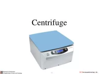
Centrifuge modelling Drum centrifuge Fixed beam centrifuge
Wave flumes on the centrifuge 50 g tests, 4m water depth, 4.5 m sand Sekiguchi et al. (2000) Viscous pore fluid - simultaneous scaling of consolidation & inertia
Centrifuge modelling Ultrasonic generator Wave Paddle Slotted partition Strong box Fluid 250 mm PWP transducers Soft soil 550 mm
Standing wave Progressive wave Anti-node Slotted partition Node Centrifuge modelling Wave Paddle Fluid PWP transducers Soft soil
Progressive waves (co = 0.13) Sub-liquefaction behaviour umax = 4 kPa
Standing waves (co = 0.20) Liquefaction behaviour umax = svo’
Critical wave loading for liquefaction Progressive Standing
Post wave loading behaviour Post wave pore pressures Surface settlement
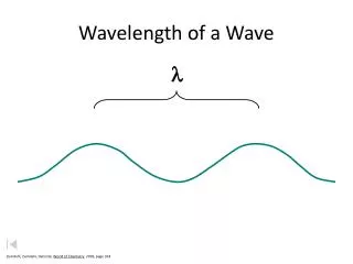
Theoretical Basis Wave surface elevation where S0 is the displacement of the board at the water level The dispersion relationship where
Wave pressure at flume base Amplitude of wave pressure
Limitations 1. The real soil is not an ideal poro-elastic body 2. The theoretical model is applicable to semi- infinite soil, but the model soil in the centrifuge is of finite depth. 3. The influence of structures is not accounted for 4. Particle movement not accounted for
Scaling factors in centrifuge Basic parameters Acceleration g: N Model length scale, H, h, etc: 1/N Prototype soil materials used in the model Density ρ: 1 Particle size d: 1
Scaling factors in centrifuge Derived parameters Wave period T: 1/N Wave number k: N Fluid pressure: 1 Fluid flow velocity: 1 Inertia time scale: 1/N Laminar flow time scale: 1/N2 By using pore fluid with a high viscosity (N times higher) such as silicone oil, the laminar flow scale can be made to be 1/N
Paddle Design Dimensions of the strong box Japan Dundee (Sekiguchi et al. 1998) Length (mm) 550 1600 Height (mm) 250 680 Width (mm) 100 276 Wave generator Quasi-Flap Type Quasi-Flap Type
Paddle and operation (1) AC servo motor (4) Crank shaft (2) Reduction wheel (5) Wave paddle (3) Attachment wheel (6) Wave channel
Typical operating conditions Japan Dundee Wave height: 10-23 mm 5-40 mm Wave frequency: 11 Hz 5-15 Hz Water depth: 90 mm 100-300 mm Sand bed thickness: 100mm 100-200mm Centrifugal accel.: 50 25-50 (? less)
Applications / Collaboration • Validation against large flume data • Validation/calibration of numerical models • Different soils: sand/silt/clayey/gassy? • Small structures: cylinder/sphere/cube (surface & buried) • Large structures: caisson/breakwater/cliff