Download
1 / 30
400 likes | 1.18k Views
MALVINO & BATES. ELECTRONIC PRINCIPLES. SEVENTH EDITION. Chapter. 6. Bipolar Junction Transistors. Topics Covered in Chapter 6. Unbiased transistor Biased transistor Transistor currents The CE connection The base curve. Topics Covered in Chapter 6 (Continued). Collector curves

E N D
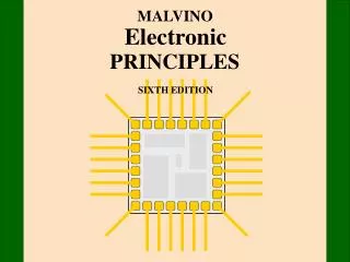
MALVINO & BATES ELECTRONIC PRINCIPLES SEVENTH EDITION
Chapter 6 Bipolar Junction Transistors
Topics Covered in Chapter 6 • Unbiased transistor • Biased transistor • Transistor currents • The CE connection • The base curve
Topics Covered in Chapter 6(Continued) • Collector curves • Transistor approximations • Reading data sheets • Surface mount transistors • Troubleshooting
Unbiased transistor • Three doped regions: emitter, base, and collector • Two pn junctions: emitter-base and base-collector • NPN or PNP • Silicon or germanium
The bipolar junction transistor has 3 doped regions. N COLLECTOR (medium doping) P BASE (light doping) N EMITTER (heavy doping)
Biased transistor • Forward bias the emitter diode • Reverse bias the collector diode
In a properly biased NPN transistor, the emitterelectrons diffuse into the base and then go on to the collector. RC N VCE RB P VCC N VBE VBB
Transistor currents • The ratio of collector current to base current is current gain (βdc or hFE) • Current gain is typically 100 to 300
IC IC IB IB IE IE IC IC bdc = adc = IB IE Conventional flow Electron flow IE = IC + IB IC @ IE IB << IC
The CE connection • The emitter is grounded or common • The base-emitter acts like a diode • The base-collector acts like a current source that is equal to βdc times the base current
The common emitter connection has two loops: the base loop and the collector loop. RC collector loop RB VCE VCC base loop VBE VBB
Subscript notation • When the subscripts are the same, the voltage represents a source (VCC). • When the subscripts are different, the voltage is between two points (VCE). • Single subscripts are used for node voltages with ground serving as the reference (VC).
Base curve • Graph similar to that of a diode • Diode approximations are used for analysis (typically - ideal or second)
The base circuit is usually analyzed with the same approximation used for diodes. VBB - VBE RC IB = RB VCE VCC RB VBE VBB
100 mA 80 mA 60 mA 40 mA 20 mA 0 mA A graph of IC versus VCE (Note that each new value of IB presents a new curve.) 14 12 10 IC in mA 8 6 4 2 6 16 2 4 10 12 0 14 18 8 VCE in Volts This set of curves is also called a family of curves.
Regions of operation • Active - - - used for linear amplification • Cutoff - - - used in switching applications • Saturation - - - used in switching applications • Breakdown - - - can destroy the transistor and should be avoided
Transistor circuit approximations • First: treat the base-emitter diode as ideal and use bIB to determine IC. Use for troubleshooting. • Second: correct for VBE and use bIB to determine IC. • Third (and higher): correct for bulk resistance and other effects. Usually accomplished by computer simulation. Use for design work.
The second approximation: bdcIB VBE = 0.7 V VCE
VBB - VBE IB = RB 5 V - 0.7 V = 43 mA IB = RC 100 kW 100 kW VCC RB VBE = 0.7 V 5 V VBB
IC = bdc IB IC = 100 x 43 mA = 4.3 mA RC 100 kW bdc = 100 VCC RB IB = 43 mA 5 V VBB
VRC = IC x RC VRC = 4.3 mA x 1 kW = 4.3 V 1 kW RC IC = 4.3 mA 100 kW 12 V VCC RB IB = 43 mA 5 V VBB
IC = 4.3 mA VCE = VCC - VRC VCE = 12 V - 4.3 V = 7.7 V 1 kW RC VCE 100 kW 12 V VCC RB IB = 43 mA 5 V VBB
Reading transistor data sheets • Maximum ratings on voltage, current, and power • Power transistors dissipate more than 1watt • Temperature can change the value of a transistor’s characteristics
Typical Breakdown Ratings • VCBO = 60 V • VCEO = 40 V • VEBO = 6 V • Note: these are reverse breakdown ratings with one transistor leg open (e.g. VCBO is voltage collector to base with emitter open)
A graphic view of collector breakdown 14 12 10 IC in mA 8 6 4 2 0 50 VCE in Volts
Typical Maximum Ratings • IC = 200 mA dc • PD = 250 mW (for TA = 60 oC) • PD = 350 mW (for TA = 25 oC) • PD = 1 W (for TC = 60 oC)
Data sheet hFE “On Characteristics” IC in mA hFE(min) hFE(max) 0.1 40 ___ 1 70 ___ 10 100 300 50 60 ___ 100 30 ___
Surface-mount transistors • A variety of package styles (three-terminal gull-wing is typical) • Some SMTs can dissipate1 watt or more • Some SMTs house multiple transistors
Troubleshooting • Look for gross voltage errors. • First approximation and mental estimates will usually suffice. • Resistors generally don’t short but circuit boards can. • Circuit boards can and do open. • Junctions can and do short. • Junctions can and do open.