Download
1 / 34
340 likes | 413 Views
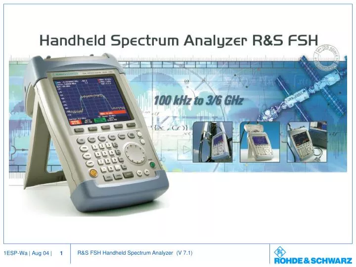
Handheld Spectrum Analyzer R&S FSH. Application Areas. General Purpose Spectrum Analysis Service Maintenance Simple lab applications Installation and Maintenance of Transmitter Stations Power measurement Measurement of antenna SWR Measurement of cable faults.

E N D
Handheld Spectrum Analyzer R&S FSH Application Areas • General Purpose Spectrum Analysis • Service • Maintenance • Simple lab applications • Installation and Maintenance of Transmitter Stations • Power measurement • Measurement of antenna SWR • Measurement of cable faults
Handheld Spectrum Analyzer R&S FSH Application Areas cont. • Field-strength Measurement • Measurement of interferer • Measurement of useful signals • Precompliance EMC Applications • Signal Monitoring
NEW NEW Handheld Spectrum Analyzer R&S FSH Model Overview
Handheld Spectrum Analyzer R&S FSH • Specifications • Frequency range 100 kHz to 3/6 GHz • Resolution bandwidths 1 kHz to 1 MHz (R&S FSH3 model13) • 100 Hz to 1 MHz (R&S FSHx Model 03/23/06/26) • Video bandwidths 10 Hz to 1 MHz • Displayed average noise floor • FSH3 model 13 <-105 dBm, typ. -114 dBm (1 kHz RBW) • FSHx model 03/06/23/26<-130 dBm, typ. -135 dBm (100 Hz RBW) • Third order intercept > 10 dBm, typ. 13 dBm • Detectors sample, max-peak,min-peak, auto-peak, RMS • SSB phase noise <-100 dBc(1 Hz) @100 kHz offset • Level accuracy <1.5 dB typ. 0.5 dB
Handheld Spectrum Analyzer R&S FSH • Specifications cont. • Display 5.7”, VGA color display, 320 x240 pixels • Power Consumption <7 W (including TG) • Battery operating time up to 4 h • Weight 2.5 kg
NEW Handheld Spectrum Analyzer R&S FSH • Standard Functions • Channel-power measurement • TDMA-power measurement • Occupied bandwidth measurement • Field strength measurement • Channel tables • Frequency counter with 1 Hz resolution • 6 Marker or delta-marker, noise marker • Limit line monitoring • External Trigger IN/ external REF IN • AM/FM Demodulator (earphone connector)
NEW Handheld Spectrum Analyzer R&S FSH • Options for R&S FSH, all models • Power sensor 10 MHz to 8 GHz • Power sensor 10 MHz to 18 GHz • Directional power sensor 200 MHz to 4 GHz • Remote Control via RS232 interface • Receiver mode • Options for R&S FSH with tracking generator (model 13/23/26) • VSWR Bridge (10 MHz to 3 GHz) • Vector reflection and transmission measurement • Distance-to-fault measurement
TDMA Power • Functions • Burst power measurement in time domain • Ext.Trigger and Video Trigger • Predefined settings for GSM/EDGE • User definable settings • Auto level adjust
Channel Power • Functions • Channel power measurement using RMS Detector • Predefined settings for 3GPP, cdmaOne, CDMA2000 1x • User definable settings • Auto level adjust
Occupied Bandwidth • Functions • Measuring the occupied bandwidth, which is defined as the bandwidth in which a specified percent (99 %) of power is transmitted. • Predefined settings for 3GPP, cdmaOne, CDMA2000 1x • User definable settings • Auto level adjust
Field Strength Measurements • Functions • Electrical field strength is directly indicated in dBµV/m • Two different transducer factors available • for Antenna • for correction of ext. cables, attenuators, amplifiers • easy combination of both transducer types • FSHView provides: • Transducer factor editor • Maximum 60 data points • Transducer factors for R&S HE200 active directional antenna • Up- and download of transducer factors
NEW Channel Tables • Functions • Tuning via predefined channel tables • Display of channel number instead of frequency • Creating tables with R&S FSHView or directly • For TV, radio mobile, monitoring applications • FSHView provides: • Channel tables editor • Maximum 15 sub-ranges per table • TV channel tables for virtually the entire world • Up- and download of channel tables
NEW Receiver Mode • Functions • For monitoring and precompliance EMC applications • Level measurement at a predefined frequency using the selected measurement time and bandwidth and the set detector • Peak-, average-, RMS-, quasi-peak-detector • 200 Hz, 9 kHz,120 kHz and 1MHz CISPR bandwidths (-6 dB) • Scan mode for automatic measurement over a defined frequency range or in defined channels • Requirements • R&S FSH (all models) • R&S FSH-K3 Receiver Mode
Limit Value Monitoring • Limit Lines • User definable upper and lower limit lines • Limit lines with pass and fail function • R&S FSHView provides: • Limit line editor • Maximum 25 data points • Up- and download of limit lines via R&S FSHView
Scalar Network Analysis • Functions • Transmission measurements • Return loss measurements • Reflection (VSWR) measurements • Calibration routines • Storage of calibration data • Requirements : • R&S FSH with tracking generator • R&S FSH-Z2 VSWR bridge
Vector Network Analysis • Better performance compared with scalar measurement • Up to 20 dB more dynamic range for transmission measurement • Higher measurement accuracy for reflection measurement • Smith-chart • Requirements : • R&S FSH with tracking generator • R&S FSH-Z2 VSWR bridge • R&S FSK-K2 vector reflection and transmission measurement
Vector Network Analysis • Functions • Smith-chart for vector reflection measurement • Limit line with pass and fail function
Comparison of Vector and Scalar Transmission Measurement • Scalar measurement of transmission function of a bandpass filter • Vector measurement of transmission function of a bandpass filter with clearly wider dynamic range ! !
Comparison of Vector and Scalar Reflection Measurement • Measurement uncertainty for scalar reflection measurement (Directivity 30 dB) • Measurement uncertainty for vector reflection measurement (correctedDirectivity 43 dB)
One-Port Cable Loss Measurement • Functions : • Easy cable loss measurement on installed long cables • Cable loss calculation from the average of the maximum and minimum values • Loss at specific frequencies can be determined with one or more markers • Requirements : • R&S FSH with tracking generator • R&S FSH-Z2 VSWR bridge • R&S FSK-K2 vector reflection and transmission measurement
Distance to Fault Measurement • Functions • Get tabular or graphic display of cablefaults versus distance • Cable length from 3m to 300m • User definable cable types • Less calibration effort, only one calibration standard necessary • Storage of calibration data • Requirements • R&S FSH with tracking generator • R&S FSH-B1 Distance to fault measurement • R&S FSH-Z2 VSWR bridge
Distance to Fault Measurement cont. • 1024 measurement points and zoom function provide high distance resolution Measurement on two cables (10m + 6m) withBNC to N adapter Contact of the two cables at the connecting point measured with high resolution (BNC-N to N adapter, length approx. 10 cm)
Power Meter Function • Specs • Frequency range 10 MHz to 8 /18 GHz • 90 dB dynamic range (-67dBm to +23 dBm) • Signal weighting : true rms • Absolute uncertainty < 2.5 % (0.11 dB) • Measurement of absolute or relative power • Read-out in dBm or linear • Requirements • R&S FSH (all models) • R&SFSH-Z1 Power sensor • R&S FSH-Z18 Power sensor
Directional Power Measurement with R&S FSH • Functions • Simultaneously measurement of forward power and reflection on transmitters • Measurement under operational conditions up to 120 W • Indication of reflection in return loss (dB) or SWR • Suitable for digital standards GSM,EDGE, 3GPP WCDMA, cdmaOne, cdma2000 1x, DVB-T, DAB • Requirements • R&S FSH (all models) • R&S FSH-Z44 Directional power sensor
Directional Power Sensor R&S FSH-Z44 • Specifications
Antenna R&S FSH-Z44 Transmitter Directional Power Measurement with R&S FSH
Remote Control of R&S FSH • Requirements • R&S FSH (all models) • R&SFSH-K1 remote control via RS232 interface • Specs • the FSH-K1 option offers remote control commands via RS232 interface for all essential FSH functions
Handheld Spectrum Analyzer R&S FSH • Documentation • Internal Memory Storage of 100 results • including instrument • setups • Printer Interface Deskjet, Laserjet, • Epson Fx Postscript • Windows Software R&S FSHView
R&S FSHView Software • Features : • Rapid and simple data transfer • Download of screenshots • Data export in PCX, BMP, PNG, WMF, ASCII and MS Excel format • On-line display of measurements • Up- and download of settings • Definition and editing of cable models, limit lines, transducer factors, channel tables • MS Winword Macro for easy documentation • Connection to PC via optical RS-232 interface
AF Output RF Input N-female External Trigger-Input/ External REF-Input BNC-female optical RS232 Interface Power Sensor Input, SWR Bridge Control Power Adapter Generator Output N-female Interfaces of R&S FSH (with Tracking Generator)
NEW NEW R&S FSH Accessories for Field-Use • 12 V Car Adapter R&S FSH-Z21 • Transit Hardcase R&S FSH-Z29 • Combined Open/Short/Load Calibration Standard R&S FSH-Z29 • Soft Carrying Bag R&S FSH-Z25
R&S FSH options and their applications • Standard function; *) R&S FSH-K2 required