Download

1 / 42
420 likes | 519 Views
Device models. Mohammad Sharifkhani. A model for manual analysis. -4. x 10. 2.5. VGS= 2.5 V. Early Saturation. 2. VGS= 2.0 V. 1.5. Linear Relationship. (A). D. I. VGS= 1.5 V. 1. VGS= 1.0 V. 0.5. 0. 0. 0.5. 1. 1.5. 2. 2.5. V. (V). DS.

E N D
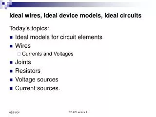
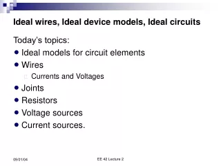
Device models Mohammad Sharifkhani
-4 x 10 2.5 VGS= 2.5 V Early Saturation 2 VGS= 2.0 V 1.5 Linear Relationship (A) D I VGS= 1.5 V 1 VGS= 1.0 V 0.5 0 0 0.5 1 1.5 2 2.5 V (V) DS Current-Voltage RelationsThe Deep-Submicron Era
5 u = 10 sat ) s / m ( n u x = 1.5 x (V/µm) c Velocity Saturation Constant velocity Constant mobility (slope = µ)
Perspective I D Long-channel device V = V GS DD Short-channel device V V - V V DSAT GS T DS
-4 x 10 -4 x 10 6 2.5 5 2 4 1.5 (A) 3 (A) D D I I 1 2 0.5 1 0 0 0 0.5 1 1.5 2 2.5 0 0.5 1 1.5 2 2.5 V (V) V (V) GS GS ID versus VGS linear quadratic quadratic Long Channel Short Channel
-4 -4 x 10 x 10 2.5 6 VGS= 2.5 V VGS= 2.5 V 5 2 Resistive Saturation VGS= 2.0 V 4 VGS= 2.0 V 1.5 (A) (A) 3 D D VDS = VGS - VT I I VGS= 1.5 V 1 2 VGS= 1.5 V VGS= 1.0 V 0.5 1 VGS= 1.0 V 0 0 0 0.5 1 1.5 2 2.5 0 0.5 1 1.5 2 2.5 V (V) V (V) DS DS ID versus VDS Long Channel Short Channel
Unified model • Model presented is compact and suitable for hand analysis. • Still have to keep in mind the main approximation: that VDSat is constant . • When is it going to cause largest errors? • When E scales – transistor stacks. • But the model still works fairly well.
Velocity saturation Smaller EcL Smaller VDsat Saturates quicker
Output resistance • Slope in I-V characteristics caused by: • Channel length modulation • Drain-induced barrier lowering (DIBL) • Both effects increase the saturation current beyond the saturation point • The simulations show approximately linear dependence of Ids on Vds in saturation.
Transistor stacks (Velocity sat.) NAND Suffers less from VS In NAND VDsat is larger
Velocity Saturation • How about NAND3? • IDSat = 1/2 of inverter IDSat (instead of 1/3) • How about PMOS networks? • NOR2 – 1.8x, NOR3 – 2.4x, NOR4 - 3.2x • What is ECL for PMOS?
Alpha power law • This is not a physical model • Simply empirical: • Can fit (in minimum mean squares sense) to variety of α’s, VTh • Need to find one with minimum square error – fitted VTh • can be different from physical • Can also fit to α = 1 • What is VTh?
I-V Curves Triode Vel. Sat. Regular sat.
-4 x 10 0 -0.2 -0.4 (A) D I -0.6 -0.8 -1 -2.5 -2 -1.5 -1 -0.5 0 V (V) DS A PMOS Transistor VGS = -1.0V VGS = -1.5V VGS = -2.0V Assume all variables negative! VGS = -2.5V
MOS capacitance • The capacitance of the MOS affects the dynamic behavior of a circuit • Speed Caps • Proper modeling is needed
Polysilicongate Source Drain W x x + + n n d d Gate-bulk L d overlap Top view Gate oxide t ox + + n n L Cross section The Gate Capacitance
Gate Capacitance Cut-off Resistive Saturation Most important regions in digital design: saturation and cut-off
Diffusion Capacitance Channel-stop implant N 1 A Side wall Source W N D Bottom x Side wall j Channel L Substrate N S A

![Semiconductor Device Noise Models Based on Semiclassical Transport [5115-3]](https://cdn4.slideserve.com/661128/slide1-dt.jpg)