Download
1 / 19
240 likes | 455 Views
Geotechnical investigations on parts of Tunnel between Ramappa Tank and Dharmasagar Tank, J. Chokka Rao Devadula Lift Irrigation Scheme, Phase-III, Warangal District, Telangana State by G.J.S. Prasad Superintending Geologist Geological Survey of India Southern Region Hyderabad.

E N D
Geotechnical investigations on parts of Tunnel between Ramappa Tank and Dharmasagar Tank, J. Chokka Rao Devadula Lift Irrigation Scheme, Phase-III, Warangal District, Telangana State by G.J.S. Prasad Superintending Geologist Geological Survey of India Southern Region Hyderabad
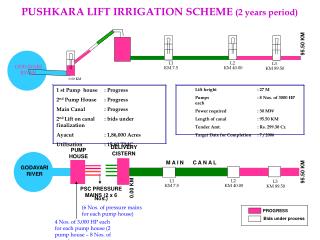
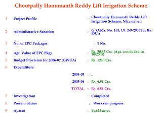
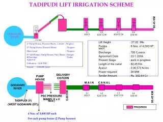
J. Chokka Rao Devadula Lift Irrigation Scheme (JCRDLIS) • J. Chokka Rao Devadula Lift Irrigation Scheme (JCRDLIS) envisages lifting 38.16 TMC of water from the Godavari River near Gangaram (V), Eturunagaram (M), Warangal District to irrigate an area of 6.21 lakh acres in drought prone areas of Karimnagar, Warangal and Nalgonda Districts of Telangana in a phased manner. • Phase-I: It includes construction of a single MS pipe line of 2.5m diameter with 10 Cumecs discharge to lift 5.18TMC of water for a length of 135km from the River Godavari near Gangaram (V), Eturinagaram (M) to R.S. Ghanpur (V&M) and improving of existing tanks Bheemghanpur, Pulkurthy, Dharmasagar and R.S. Ghanpur) enroute to supply water to drought prone areas of Warangal district, Andhra Pradesh. • Phase-II: It encompasses construction of a single pipe of 3.0m diameter with 14 Cumecs of discharge to lift 7.25TMC of water from Gangaram and raising/improving of earth bunds at Bheemghanpur, Salivagu, Dharmasagar, Gandiramaram, Bommakur, R.S.Ghanpur, Ashwaraopally, Chittakodur and Tapaspally covering a length of 220Km. The work is under progress. • Phase-III: The balance of 23.81 TMC of JCRDLIS is proposed to be lifted by means of tunnels/canals instead of M.S. Pipe line from the River Godavari near Gangaram(V), Eturinagaram (M) to R. S. Ghanpur (17°51”:79°23”) covering a length of 200Km under this phase. It also includes rising of new earth bunds and using of existing reservoirs enroute.
J. Chokka Rao Devadula Lift Irrigation Scheme, Warangal District J. Chokka Rao Devadula Lift Irrigation Scheme (JCRDLIS) envisages to lift 38.16 TMC of water from the Godavari River near Gangaram (V), Eturinagaram (M), Warangal District to irrigate an area of 6.21 lakh acres in drought prone areas of Karimnagar, Warangal and Nalgonda Districts of Telangana in a phased manner. As an integral part of the Phase-III, the balance of 23.81 TMC ofJCRDLIS is proposed to be lifted by means of tunnels/canals instead of M.S. Pipe line from the River Godavari near Gangaram(V), Eturinagaram (M) to R. S. Ghanpur covering a length of 200Km under this phase. It also includes rising of new earth bunds and using of existing reservoirs enroute.
Salient features • Geotechnical assessment and geological logging parts of tunnel from Ramappa Tank to Dharmasagar Tank was carried out. • In the mapped reach the tunnel is excavated through medium to coarse grained hard, grey and pink granite, forming the tunneling media of the tunnel. The tunnel reach is traversed by three sets of joints and a sub horizontal joint. • The excavations are dry condition during course of investigations. In this reach, the rock covers over the crown of the tunnel ranging from 58 to 78m. • Length of pressure tunnel : 54.88 km • Inlet portal : 18°12’40.23”;79°54’27.9”; 56N/16 NE • Outlet portal : 18°00’14.2”;79°26’7.29”; 56N/8 SE • Bearing of the tunnel : N65°E- S65°W. • Shape of tunnel : ‘D’ Shape • Finished Diameter of tunnel : 5.6 m • Invert level at inlet : RL. 187.605m • Invert level at outlet : RL.163.350m
Discussion and suggestions: • 3D geological mapping and geotechnical assessment of parts of tunnel was carried out, indicated that grey and pink granite intruded by basic dyke, quartz vein and pegmatite veins forms the tunneling medium in the mapped reach. The rock mass is traversed by three sets of joints and a random joint. • Among them two sets are mostly aligned more or less perpendicular to the tunnel alignment which is the feature considered favourable for tunneling and they are predominantly tight with occasional openings, rough, irregular to planar, stained to unstained, discontinuous to continuous in nature. • In general, most of the mapped reaches are the tunnel exhibits dry condition with occasional dripping zones. • As the sheet joints/sub horizontal joints/low dipping joints are quite common in granitic tunneling medium leading to the formation of slabbing/flat roof at crown and same was noticed at places in the tunnel segments due to their disposition with respect to the tunnel axis.
The geotechnical assessment, evaluation and rock mass characterization of tunneling media for the mapped reaches have been classified based on Grimstad and Barton, 1993, reproduced from Palmstrom and Broch, 2006 chart for stabilizing the crown and excessive loosening of rock blocks along intersecting joints as an immediate support after excavation and the tunneling media categorized as Class B (Good), and C (Fair), based on the calculated Tunnel Quality Index ‘Q’. • As the cover over crown is more than 3 dia of the excavated tunnel in the mapped reaches with stand up time is more than 6 months without any major rock fall/ collapse of tunnel etc., the supporting measures for the excavated tunnel for the “Good” reaches, may be provide with random bolts (3.5m long, 25mm dia) with localized shotcreting. • In the “Fair” reaches, pattern rock bolts (3.5m long, 25mm dia, 3m spacing) may be provided along with shotcreting to protect the crown of the tunnel till the permanent lining is done. • Suggested to provide rib supports for 5m in all directions of the “T” junctions with 1m spacing to accommodate the loads over the tunnel.
As soon as the full arch is opened, a continuous support (lining) is required for entire width of the chamber. Hence, it is suggested to provide a continuous PCC lining for the entire tunnel as per BIS Codes. • Contact grouting from spring to crown portion and consolidation grouting for invert portion is also suggested in staggered fashion with 3m interval after placing PCC lining. • As the tunnel is not having free board (pressure tunnel) the drainage holes are not suggested however, provide temporary drainage holes at the seeped zones and divert the seepage to the side drains/pipes till the permanent lining is done. • Instrumentation may be installed as per standards.
Collection of geological data from the tunnel grade rock mass