Download
1 / 11
110 likes | 334 Views
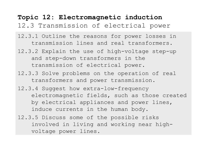
12.3.1 Outline the reasons for power losses in transmission lines and real transformers. 12.3.2 Explain the use of high-voltage step-up and step-down transformers in the transmission of electrical power. 12.3.3 Solve problems on the operation of real transformers and power transmission.

E N D
12.3.1 Outline the reasons for power losses in transmission lines and real transformers. 12.3.2 Explain the use of high-voltage step-up and step-down transformers in the transmission of electrical power. 12.3.3 Solve problems on the operation of real transformers and power transmission. 12.3.4 Suggest how extra-low-frequency electromagnetic fields, such as those created by electrical appliances and power lines, induce currents in the human body. 12.3.5 Discuss some of the possible risks involved in living and working near high-voltage power lines. Topic 12: Electromagnetic induction12.3 Transmission of electrical power
Outline the reasons for power losses in transmission lines and real transformers. Observe the simplified electrical grid: Topic 12: Electromagnetic induction12.3 Transmission of electrical power FYI Power is lostas heatduring transformer step-up and -down of the voltage due to eddy currents. Power is lost as heat in the lines during the current transmission due to internal resistance.
heat loss in transmission lines P = I2R Outline the reasons for power losses in transmission lines and real transformers. For transmission lines, the gauge of wire is determined in trade-off between cost of large-diameter (low resistance) wire, and cost of power lost due to low- diameter (high resistance) wire. Topic 12: Electromagnetic induction12.3 Transmission of electrical power EXAMPLE: Many transmission lines are made of aluminum (having a resistivity of 5.210-8 m) reinforced with steel (see picture). (a)What is the cross-sectional area of the cable? SOLUTION: The diameter is d = (4 in )(2.54 cm in-1) = 10 cm = 0.1 m. The area is then A = d2/4 = (0.1)2/4 = 0.008 m2.
heat loss in transmission lines P = I2R Outline the reasons for power losses in transmission lines and real transformers. For transmission lines, the gauge of wire is determined in trade-off between cost of large-diameter (low resistance) wire, and cost of power lost due to low- diameter (high resistance) wire. Topic 12: Electromagnetic induction12.3 Transmission of electrical power EXAMPLE: Many transmission lines are made of aluminum (having a resistivity of 5.210-8 m) reinforced with steel (see picture). (b)Assuming the cable is all aluminum, find the resistance of a 150 km section. SOLUTION: Use R = L/A: R = L/A = (5.210-8)150000/0.008 = 1 .
Outline the reasons for power losses in transmission lines and real transformers. For real transformers, there are eddy currents (Ieddy f2)and hysteresis currents (Ihystf) both of which are set up by Faraday’s law due to the magnetic flux change that is part of AC circuits. Both of these currents produce I2R heat loss. Hysteresis losses are less significant than eddy losses. Recall from Topic 12.2 that eddy currents can be minimized by lamination of the transformer core. There is also the I2R heat loss simply due to the resistance of the length of wire in the windings in the primary and secondary coils. Topic 12: Electromagnetic induction12.3 Transmission of electrical power
Explain the use of high-voltage step-up and step-down transformers in the transmission of electrical power. Recall that heat loss is determined by P = I2R. Since the resistance R of the transmission cable is fixed once its diameter has been chosen, the only other way to reduce power loss is to reduce the current I going through the cable. Since P = VI, if we want to minimize I we can do so if we increase V, thus maintaining the power P that is to be delivered. This is the idea behind the use of the step-up transformer at the generation side of the power grid. Topic 12: Electromagnetic induction12.3 Transmission of electrical power
Explain the use of high-voltage step-up and step-downtransformers in the transmission of electrical power. Since the high voltage used for transmission is very dangerous, at the end of the transmission it is brought back down to a safer level through the use of a step-down transformer. Topic 12: Electromagnetic induction12.3 Transmission of electrical power
Solve problems on the operation of real transformers and power transmission. PRACTICE: The 150 km cable whose resistance was calculated previously to be 1 is designed to deliver 270 MW to a community. (a) If the transmission occurs at 138 kV, what is the current and the heat loss? (b) If the transmission occurs at 765 kV, what is the current and the heat loss? SOLUTION: Use P = VI ( or I = P/V ) and P = I2R. (a) I = P/V = 270106/138103 = 2000 A (1957 A). P = I2R = 19572(1) = 3.8106 W = 4 MW. This is a 4/270 = 0.01 = 1% heat loss. (b) I = P/V = 270106/765103 = 350 A (353 A). P = I2R = 3532(1) = 1.2105 W = 0.1 MW. This is 0.1/270 = 0.0004 = 0.04% heat loss. Topic 12: Electromagnetic induction12.3 Transmission of electrical power
Solve problems on the operation of real transformers and power transmission. Topic 12: Electromagnetic induction12.3 Transmission of electrical power
Suggest how extra-low-frequency electromagnetic fields, such as those created by electrical appliances and power lines, induce currents in the human body. The frequency of transmitted and home-used power is about 60 Hz, which is considered to be an extremely low frequency (ELF). The photons emitted by such ELF radiation are not energetic enough to ionize living cells, and thus cannot harm cells via ionization as alpha, beta and gamma rays can. The alternating field, however, can set up small alternating currents in the body. This is because there are both ions and polarized molecules in cellular structures which can respond to alternating electromagnetic fields according to Faraday’s law. Topic 12: Electromagnetic induction12.3 Transmission of electrical power
Discuss some of the possible risks involved in living and working near high-voltage power lines. Many studies have shown that ELF fields do not harm genetic material. Studies on the effect of ELF-induced currents in living cells are inconclusive, however. Read the article Power lines link to cancer to see evidence that induced currents do increase the incidence of childhood leukemia. Other obvious risks are danger of electrocution. Topic 12: Electromagnetic induction12.3 Transmission of electrical power