Download
1 / 12
120 likes | 247 Views
UCHOLA Firmware and Tests. UCHOLA Design Team Anton Kapliy Mel Shochet Fukun Tang Lauren Tompkins Daping Weng Enrico Fermi Institute University of Chicago ANL, Nov. 22 2011 . Bird’s-eye view: original HOLA. (for simplicity, only the forward channel is shown). FPGA.

E N D
UCHOLA Firmware and Tests UCHOLA Design Team Anton Kapliy Mel Shochet FukunTang Lauren Tompkins DapingWeng Enrico Fermi Institute University of Chicago ANL, Nov. 22 2011 FTK Engineering Meeting at ANL A.Kapliy 11/22/2011
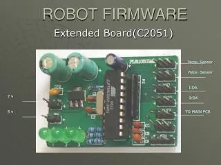
Bird’s-eye view: original HOLA (for simplicity, only the forward channel is shown) FPGA Mezzanine data port D[32] @ 50 MHz FIFO Interface to TLK D[32] @ 40 MHz TX_EN TX_DV D[16] @ 100 MHz TLK2501 serializer • FPGA provides a parallel interface to an outside SERDES device (TLK-2501), which feeds serial signal to an optical transmitter. • However, TLK-2501: • Is getting deprecated and not marketed by TI anymore • Rather expensive and hard to find among the distributors • Consumes a lot of power • Therefore, we chose to move the transceivers inside the FPGA • Budget Cyclone IV (~$40) fits the bill Serial connection via optical transceiver TLK2501 deserializer FTK Engineering Meeting at ANL A.Kapliy 11/22/2011
Bird’s-eye view: dual-output HOLA (for simplicity, only the forward channel is shown) FPGA Mezzanine data port D[32] @ 50 MHz FIFO Interface to TLK D[32] @ 40 MHz Old HOLA core TX_EN TX_DV D[16] @ 100 MHz TLK2501 wrapper Serial connection via optical transceiver • >90% of original HOLA code is unchanged. • TLK2501 wrapper emulates TLK2501 functionality: • “Plugs in” into the original HOLA core code • Implements link startup and synchronization • TLK receiver on DAQ side is oblivious to the change • Firmware created with Altera Quartus 10.1 SP1 TLK2501 deserializer Xilinx deserializer ROBIN FTK_IM FTK Engineering Meeting at ANL A.Kapliy 11/22/2011
Prototype Card Tests at Chicago: setup (1) Static optical attenuators (850 nm multimode) S32PCI64 “SOLAR” (FEMB) • PC • (Gentoo Linux) • Performs: • Reset • Control • Verification Dual-output HOLA (LSC) Two pairs of optical fibers “FILAR” (LDC + ROMB) FTK channel DAQ channel FTK Engineering Meeting at ANL A.Kapliy 11/22/2011
Prototype Card Tests at Chicago: setup (2) UCHOLA Front Panel PWR TST ERR UP0 UP1 XF0 XF1 ACT PWR TST ERR UP0 UP1 XF0 XF1 ACT PCI FILAR Card DAQ PCI SOLAR Card Four 7 dB attenuators Configuration & JTAG Ports Dual HOLA Card FTK Engineering Meeting at ANL A.Kapliy 11/22/2011
Prototype Card Tests at Chicago: setup (3) FTK Engineering Meeting at ANL A.Kapliy 11/22/2011
Prototype Card Tests at Chicago: results • Power Consumption: 0.62A@3.3V (2 Watts Total) with 2 optical transceivers. • Stress Tests: using “SLIDAS” test mode. • Pseudo-random patterns are generated inside SOLAR and sent through the DAQ and FTK fibers, which are then read out by the FILAR. • SOLAR tries to send at ~150 MB/s • PC can readout & verify only at 65 MB/s • Flow control nearly always asserted • BER= 0.7x10⁻¹⁶ with -7dB (21 days) • BER= 1x10-12with -13dB (30 minutes) • Additional Tests: • Generating data on the PC and passing it to the HOLA through the SOLAR (slow!) • SLIDAS test mode with smaller or larger S-Link frame fragments • ROD mode: pseudo-random data with ROD-like headers/trailers • Setting DAQ return lines on the FILAR and reading them out on the SOLAR 32-bit data port 2-Ch Optical Transceivers Top Side View FPGA Bottom Side View • Drop-in replacement for default HOLA: • If FTK fiber is disconnected, the HOLA automatically operates in DAQ-only mode FPGA Conf. Port JTAG PORT FTK Engineering Meeting at ANL A.Kapliy 11/22/2011
Prototype Card Tests at CERN: setup Pixel and SCT testbenches in SR1 XOFF (DAQ) ROD ROBIN I ROS (PC) Pattern generatoror real data DAQ link Duo-HOLA XOFF XOFF (FTK) FTK link XOFF (FTK) ROBIN 2 Attenuator FTK_IM replicates the data it receives from HOLA and sends it to a 2nd ROBIN. A PC reads out and validates data from both ROBINs. We control the speed of each readout to selectively exercise XOFF FTK_IM EDRO board FTK Engineering Meeting at ANL A.Kapliy 11/22/2011
Prototype Card Tests at CERN: results • Discovered that we really need a front panel for the HOLA • Otherwise, there is a danger of mechanical shorts with the BOC card • Pixel testbench: • Event rate: 10-20 KHz for >24 hours • FTK can hold the data (XOFF) for an arbitrarily long period of time without causing a timeout • This is probably just a feature of this particular SR1 testbench. • Once FTK XOFF is removed, data flow continues • SCT testbench: • Event rate: ~100 Hz (trigger problems prevented us from running faster) • FTK can hold data for up to 10 seconds at 100Hz (shorter at higher rates) • Beyond that, ROS times out, and the corresponding ROD is automatically taken out of data taking. Note that this timeout is configurable. • Need to be careful during system integration! • To prevent spurious XOFF during FTK fiber plugging/unplugging, we added a HOLA FTK_XOFF_ENA register that can be programmed through FTK LRL. • When this register is off, the FTK channel is completely passive (no effect on ATLAS) • We plan to have this register off on power-up in the default firmware FTK Engineering Meeting at ANL A.Kapliy 11/22/2011
Production Test List Assign a serial number to the card Inspect component soldering Check short/open of 6 DC powers Load Faraday cages and optical transceivers Install front panel Check DC current before FPGA configuration Load FPGA firmware Check DC current after FPGA configuration Mount UCHOLA to SOLAR board Insert all the optical fibers Start test program Fill Elog database with test results Unload UCHOLA and package it for shipping UCHOLA Front Panel PWR TST ERR UP0 UP1 XF0 XF1 ACT PWR TST ERR UP0 UP1 XF0 XF1 ACT DAQ • Total production cards: 260 • Test time needed for each card (15 minutes): • Installation and FPGA configuration: 7 minutes • Dynamic Test (return lines + BER 10-11) : 8 minutes • Total required test time: 65 Hours FTK Engineering Meeting at ANL A.Kapliy 11/22/2011
Elog Database of Production Tests hola.uchicago.edu Username: einstein Password: jjff88 Thanks to Mary Heintz • The test results including DC Power and dynamic test status for every card will be recorded in a UCHOLA Elog. • Test engineers can login in and write the notes. • The Elog will be very useful for tracking the status in the future. FTK Engineering Meeting at ANL A.Kapliy 11/22/2011
Installation plans • First batch of HOLAs will be installed during the winter 2011-2012 shutdown • Bjoern prepared a list of HOLAs necessary for the vertical slice. • Depending on the # of 45° regions, we’ll need to install 16 to 34 HOLAs 2-region option: 4-region option: • All HOLAs will be tested and entered to the eLogby mid-January 2012. • Installation planned for late January / February 2012 • Jinlong will organize these activities at CERN. I will also fly to CERN for a few weeks. FTK Engineering Meeting at ANL A.Kapliy 11/22/2011