Download
1 / 47
480 likes | 827 Views
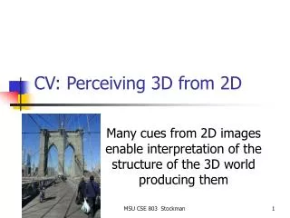
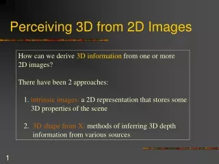
Seeing 3D from 2D Images. William and Craig 115 - 164. How to make a 2D image appear as 3D!. Output is typically 2D Images Yet we want to show a 3D world! How can we do this? We can include ‘cues’ in the image that give our brain 3D information about the scene

E N D
Seeing 3D from 2D Images William and Craig 115 - 164
How to make a 2D image appear as 3D! • Output is typically 2D Images • Yet we want to show a 3D world! • How can we do this? • We can include ‘cues’ in the image that give our brain 3D information about the scene • These cues are visual depth cues
Visual Depth Cues • Monoscopic Depth Cues (single 2D image) • Stereoscopic Depth Cues (two 2D images) • Motion Depth Cues (series of 2D images) • Physiological Depth Cues (body cues)
Monoscopic Depth Cues • Interposition • An object that occludes another is closer • Shading • Shape info. Shadows are included here • Size • Usually, the larger object is closer • Linear Perspective • parallel lines converge at a single point • Surface Texture Gradient • more detail for closer objects • Height in the visual field • Higher the object is (vertically), the further it is • Atmospheric effects • further away objects are blurrier • Brightness • further away objects are dimmer
Stereoscopic Display Issues • Stereopsis • Stereoscopic Display Technology • Computing Stereoscopic Images • Stereoscopic Display and HTDs. • Works for objects < 5m. Why?
Stereopsis The result of the two slightly different views of the external world that our laterally-displaced eyes receive.
Retinal Disparity If both eyes are fixated on a point, f1, in space, then an image of f1 if focused at corresponding points in the center of the fovea of each eye. Another point, f2, at a different spatial location would be imaged at points in each eye that may not be the same distance from the fovea. This difference in distance is the retinal disparity.
Disparity • If an object is closer than the fixation point, the retinal disparity will be a negative value. This is known as crossed disparity because the two eyes must cross to fixate the closer object. • If an object is farther than the fixation point, the retinal disparity will be a positive value. This is known as uncrossed disparity because the two eyes must uncross to fixate the farther object. • An object located at the fixation point or whose image falls on corresponding points in the two retinae has a zero disparity.
Convergence Angles +a+c+b+d = 180 +c+d = 180 - = a+(-b) = 1+2 = Retinal Disparity f1 a D1 f2 b a D2 b c d 2 1 i
Miscellaneous Eye Facts • Stereoacuity - the smallest depth that can be detected based on retinal disparity. • Visual Direction - Perceived spatial location of an object relative to an observer.
Horopters • Corresponding points on the two retinae are defined as being the same vertical and horizontal distance from the center of the fovea in each eye. • Horopter - the locus of points in space that fall on corresponding points in the two retinae when the two eyes binocularly fixate on a given point in space (zero disparity). • Points on the horopter appear at the same depth as the fixation point. Vieth-Mueller Circle
Stereoscopic Display • Stereoscopic images are easy to do badly, hard to do well, and impossible to do correctly.
Stereoscopic Displays • Stereoscopic display systems create a three-dimensional image (versus a perspective image) by presenting each eye with a slightly different view of a scene. • Time-parallel • Time-multiplexed
Two Screens Each eye sees a different screen Optical system directs each eye to the correct view. HMD stereo is done this way. Single Screen Two different images projected on the same screen Images are polarized at right angles to each other. User wears polarized glasses (passive glasses). Time Parallel Stereoscopic Display
Passive Polarized Projection Issues • Linear Polarization • Ghosting increases when you tilt head • Reduces brightness of image by about ½ • Potential Problems with Multiple Screens (next slide) • Circular Polarization • Reduces ghosting but also reduces brightness and crispness of image even more
Problem with Linear Polarization • With linear polarization, the separation of the left and right eye images is dependent on the orientation of the glasses with respect to the projected image. • The floor image cannot be aligned with both the side screens and the front screens at the same time.
Time Multiplexed Display • Left and right-eye views of an image are computed and alternately displayed on the screen. • A shuttering system occludes the right eye when the left-eye image is being displayed and occludes the left-eye when the right-eye image is being displayed.
Screen Parallax The screen parallax is the distance between the projected location of P on the screen, Pleft, seen by the left eye and the projected location, Pright, seen by the right eye (different from retinal disparity).
Screen Parallax (cont.) p = i(D-d)/D where p is the amount of screen parallax for a point, f1, when projected onto a plane a distance d from the plane containing two eyepoints. i is the interocular distance between eyepoints and D is the distance from f1 to the nearest point on the plane containing the two eyepoints d is the distance from the eyepoint to the nearest point on the screen
Screen Parallax Zero parallax at screen, max positive parallax is i, negative parallax is equal to I halfway between eye and screen
Screen Parallax and Convergence Angles • Screen parallax depends on closest distance to screen. • Different convergence angles can all have the same screen parallax. • Also depends on assumed eye separation.
How to create correct left- and right-eye views • To specific a single view in almost all graphics software or hardware you must specify: • Eyepoint • Look-at Point • Field-of-View or location of Projection Plane • View Up Direction
Basic Perspective Projection Set Up from Viewing Paramenters Y Z X Projection Plane is orthogonal to one of the major axes (usually Z). That axis is along the vector defined by the eyepoint and the look-at point.
What doesn’t work • Each view has a different projection plane • Each view will be presented (usually) on the same plane
i i What Does Work
Setting Up Projection Geometry No Look at point Eye Locations Yes Eye Locations Look at points
Screen Size The size of the window does not affect the retinal disparity for a real window. Once computed, the screen parallax is affected by the size of the display screen
Visual Angle Subtended Screen parallax is measured in terms of visual angle. This is a screen independent measure. Studies have shown that the maximum angle that a non-trained person can usually fuse into a 3D image is about 1.6 degrees. This is about 1/2 the maximum amount of retinal disparity you would get for a real scene.
Accommodation/ Convergence Display Screen
Interocular Dependance True Eyes Modeled Eyes Projection Plane Perceived Point F Modeled Point
Obvious Things to Do • Head tracking • Measure User’s Interocular Distance
Another Problem • Many people can not fuse stereoscopic images if you compute the images with proper eye separation! • Rule of Thumb: Compute with about ½ the real eye separation. • Works fine with HMDs but causes image stability problems with HTDs (why?)
Two View Points with Head-Tracking True Eyes Modeled Eyes Projection Plane Perceived Points Modeled Point
Projection Plane Perceived Point True Eyes Modeled Point E F Modeled Eyes Maximum Depth Plane Maximum Depth Plane
Can we fix this? • Zachary Wartell, "Stereoscopic Head-Tracked Displays: Analysis and Development of Display Algorithms," Ph.D. Dissertation, Georgia Institute of Technology, August 2001. • Zachary Wartell, Larry F. Hodges, William Ribarsky. "An Analytic Comparison of Alpha-False Eye Separation, Image Scaling and Image Shifting in Stereoscopic Displays," IEEE Transactions on Visualization and Computer Graphics, April-June 2002, Volume 8, Number 2, pp. 129-143. (related tech report is GVU Tech Report 00-09 ( Abstract , PDF , Postscript .) • Zachary Wartell, Larry F. Hodges, William Ribarsky. "Balancing Fusion, Image Depth, and Distortion in Stereoscopic Head-Tracked Displays." SIGGRAPH 99 Conference Proceedings, Annual Conference Series. ACM SIGGRAPH, Addison Wesley, August 1999, p351-357. (Paper: Abstract , PDF , Postscript ; SIGGRAPH CD-ROM Supplement, supplement.zip,supplement.tar.Z ).
Point of fixation Change in eyepoint separation with change in point of fixation. Centers of rotation of the eyes are assumed to be 6.4 centimeters apart.
Ghosting • Affected by the amount of light transmitted by the LC shutter in its off state. • Phosphor persistence • Vertical screen position of the image.
Ghosting (cont.) Luminance of the correct eye image ------------------------------------------------------------ Luminance of the opposite eye ghost image Extinction Ratio = Image Position RedWhite Top 61.3/1 17/1 Middle 50.8/1 14.4/1 Bottom 41.1/1 11/1
Ghosting (cont.) • Factors affecting perception of ghosting • Image brightness • Contrast • Horizontal parallax • Textural complexity
Time-parallel stereoscopic images • Image quality may also be affected by • Right and left-eye images do not match in color, size, vertical alignment. • Distortion caused by the optical system • Resolution • HMDs interocular settings • Computational model does not match viewing geometry.
Motion Depth Cues • Parallax created by relative head position and object being viewed. • Objects nearer to the eye move a greater distance
Pulfrich Effect • Neat trick • Different levels of illumination require additional time (your frame rates differ base of amount of light) • What if we darken one image, and brighten another? • http://dogfeathers.com/java/pulfrich.html • www.cise.ufl.edu/~lok/multimedia/videos/pulfrich.avi
Physiological Depth Cues • Accommodation – focusing adjustment made by the eye to change the shape of the lens. (up to 3 m) • Convergence – movement of the eyes to bring in the an object into the same location on the retina of each eye.
Summary • Monoscopic – Interposition is strongest. • Stereopsis is very strong. • Relative Motion is also very strong (or stronger). • Physiological is weakest (we don’t even use them in VR!) • Add as needed • ex. shadows and cartoons