Download
1 / 34
360 likes | 586 Views
Toroidal rotation in JET and Tore Supra Tokamaks. Toroidal rotation in JET and Tore Supra Tokamaks. João Bernardo Supervisor: Dr. Santiago Reyes Cortes Co-supervisor: Dr. João Pedro Bizarro. JET:

E N D
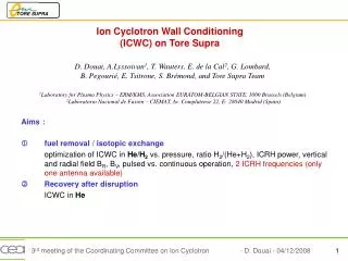
Toroidal rotation in JET and Tore Supra Tokamaks Toroidal rotation in JET and Tore Supra Tokamaks João Bernardo Supervisor: Dr. Santiago Reyes Cortes Co-supervisor: Dr. João Pedro Bizarro JET: Y. Andrew, K. Crombé, S. Reyes Cortes, G. Saibene, J. Lönnroth, T.M. Biewer, J.Ferreira, N.C. Hawkes, I. Jenkins, E. de la Luna, D. McDonald, I. Nunes, A. Salmi Tore Supra: P. Hennequin, L. Vermare, N. Fedorczak, Ö. D. Gürcan, E. Trier, N. Stuyck, C. Fenzi, J. Gunn, P. Monier-Garbet, C. Bourdelle, P. Ghendrih, X. Garbet
Outline - JET / Tore Supra - NBI - Charge-eXchange Recombination Spectroscopy (CXRS) - Results - Future work and perspectives
JET / Tore Supra Main features
JET / Tore Supra http://irfm.cea.fr/gb/iter/iter02.htm
JET / Tore Supra Joint European Torus Currently the only machine capable of operating with D-T plasma Primary task : prepare construction and operation of ITER - Act as a test bed for ITER technologies and plasma operating scenarios From 2011 onwards : FW will be of Be and W Auxiliary heating system: Neutral Beam Injection (NBI) of 35 MW Ion Cyclotron Resonance Heating (IRCH) of 10 MW Lower Hybrid Current Drive (LHCD) of 7 MW A high frequency pellet injector for plasma refuelling and for ELM pacing studies. A massive gas injection valve for plasma disruption studies. Remote handling facilities
JET / Tore Supra Superconducting field coils cooled by superfluid helium 1.8K (2) Actively cooled PFCs (water) (7) Long pulse LHCD and ICRH (14 & 15) Was equipped with a ergodic divertor and discrete set of limiters Now equipped with a Toroidal Pump Limiter (8) New generation of limiters (CIEL project in 2000) is now capable of extracting a total of 15 megawatts of power transferred by plasma particles (maximum flux density of 10 MW/m2) • 7m2 "limiter" ring with: • 576 horizontal actively cooled fingers
Outline - JET / Tore Supra - NBI - Charge-eXchange Recombination Spectroscopy (CXRS) - Results - Future work and perspectives
NBI JET / Tore Supra • JET has 16 Positive Ion Neutral Injectors (PINIs) distributed in two Neutral Injector Boxes (NIB) NIB4: 8 PINIs (4 tangential/4 normal) NIB8: 8 PINIs (4 tangential/4 normal) • Maximum injected power (D2): ~24 MW • Beam pulse length : 10 s (at high power) • Neutral Beam Enhancement (NBE) project will give ~35MW of Total Power and double the pulse length. JET plasma heating systems Tore Supra [1]: Neutral Beam Injection for diagnostic purpose : PDNBI ~ 700kW [1] A. Simonin et al., Rev. Sci. Inst., 73, 2886 (2002)
Outline - JET / Tore Supra - NBI - Charge-eXchange Recombination Spectroscopy (CXRS) - Results - Future work and perspectives
CXRS – Diagnostic principle Vessel Passive - Warm/rotating slowly SOL - Cold/not rotating Active - Hot/rotating Beams Lines of Sight (LOS)
CXRS - JET Pixel Eleonora talk H0 + Az+ → H+ + A*(Z-1)+ D0 + C6+ → D+ + C5+ Transition between Rydberg states Δn=1 (n=8 → 7) 5290.6Å Doppler broadening → Ti Doppler shift → vφi/vθi CVI-CX Active Charge eXchange (ACX) Intensity Ph m-2 sr-1 nm-1 s-1 CVI passive Passive Charge eXchange (PCX) CIII edge line BeII
CXRS - JET Pixel λT λobs Vφ/θ CVI-CX Active Charge eXchange (ACX) Intensity Ph m-2 sr-1 nm-1 s-1 Ti
Outline - JET / Tore Supra - NBI - Charge-eXchange Recombination Spectroscopy (CXRS) - Results - Future work and perspectives
Results - JET Plasma operation with Type-I ELMs to reach Q=10 for ITER [2]. Control Type-I ELMs - DIII-D [3] - TCV [4] - ASDEX-Upgrade [5] Improve the understanding of the physics of ELMs Reports from JT-60U [6] have shown that neutral beam injection (NBI) in counter-current direction alters vφ decreasing the fELM. Therefore, further understanding of ELM behavior and the relationship with toroidal velocity is relevant for ITER Effect of vφ on fELM. Varying δr JET δr = 0.08-3% ITER δr ~0.5% (FI compensation) TF ripple breaks the axisymmetry of the magnetic field, enhancing particles losses of fast and thermal ions [7,8] affecting vφ. [2] ITER Physics Basis, Nucl. Fusion, 47, S18 (2007) [3] T.E. Evans et al., PRL, 92, 235003 (2004) [4] A.W. Degeling et al., PPCF, 45, 1637 (2003) [5] H. Urano et al., PPCF 45, 1571 (2003) [6] Y. Sakamoto et al., PPCF, 46, A299 (2004) [7] P. de Vries et al., Nucl. Fusion, 48, 035007 (2008) [8] H. Urano et al., Nucl. Fusion, 47, 706 (2007)
Results – JET (TF ripple) Ripple in tokamaks can be compared to a ripple on the water surface Finite number of coils JET has 32 TF coils δr varied by configuring different currents to the odd and even set of coils δr = [Bmax - Bmin)] / [Bmax+ Bmin)] magnetic field along the circle for which the major radius R and the vertical coordinate Z are constant δr ~ 0.08%-3% contour plot of δr with the current ratio of odd/even = 0.52 (δr = 1%)
Results – JET (TF ripple) TRANSPORT AND LOSSES INDUCED BY TF RIPPLE The toroidal field ripple enhances the transport of fast ions by modifying their guiding centre orbit. Two mechanisms: - Ripple-trapped transport - Ripple-banana diffusion Operational boundaries depends on δr, plasma shape and on plasma parameters (ne and Ip) T. Johnson et al., “HALEKAR Modelling of Fast Particle Transport and Losses with TF Ripple in JET”, 10th IAEA proceedings
Results - JET Similarity of plasma paremeters, however Dα different (δr=0.75%) (δr=0.08%) I (105 A) B (T) ne (1019 m-3) Wdia (MJ) Dα (1016 s-1cm-2sr-1) Input Power (107 W) Ip ~ 2.4 MA Ip ~ 2.4 MA Bt ~ 2.4 T Bt ~ 2.4 T ne ~ 7x10¹⁹ m-3 ne ~ 6.8x10¹⁹ m-3 Wdia ~ 6 MJ Wdia ~ 5 MJ NBI Norm ~9.5MW NBI Tang ~6MW ICRH ~1MW NBI Norm ~9.5MW NBI Tang ~6MW ICRH ~1MW Time windows for CXSE measurements (Δt=50ms) and ELM frequency t(s)
Results - JET Pedestal location 4 3 2 1 0 LCFS 200 150 100 50 0 LCFS ― Ti (edge CX) ― Te (HRTS) - - ne (HRTS) T (keV) vφ (km/s) 3.5 3.6 3.7 3.8 3.9 R(m) 3.5 3.6 3.7 3.8 3.9 R(m) Toroidal velocity from edge CX was extracted from pedestal location
Results - JET Increase in δr leads to a degradation in the total pedestal pressure
Results - JET pped presents lower values as the rotation decrease
Results - JET pped decrease as the fELM increase It seems that ripple is not directly influencing the ELM frequency.
Results - JET Velocity amplitude seems to be linked with felm, not ripple Why? Results indicate that absolute vφ is influencing the fELM
Results - JET Higher well depth for low ripple JET Pulse # 77078 (δr=0.08%) # 77084 (δr=0.75%) 105 (V m-1) ▬77078 (δr=0.08%) ▬77084 (δr=0.75%) Er and hence the ωExB is a key factor to reduce turbulent transport and stabilization of MHD activity. Er can be written as: Er 105 (V m-1) ▬77078 (δr=0.08%) ▬77084 (δr=0.75%) ~60kV/m Well depth: ~ 60 kV/m 77078 (δr=0.08%) ~ 40 kV/m 77084 (δr=0.75%) ▬77078 (δr=0.08%) ▬77084 (δr=0.75%) ~40kV/m ρ ρ
Results - JET ωExB is higher for low ripple [9] Futher work required: MHD Stability ▬77078 (δr=0.08%) ▬77084 (δr=0.75%) [9] T.S. Hahm, Phys. Plasmas2 p. 1648, 1995
Results - JET A working model for ELMs is that they are intermediate toroidal mode number, n~5-30, peeling-ballooning modes. ELMs event occur when the growth rates of the intermediate n MHD modes become sufficiently large [10]. Peeling-ballooning modes are affected by: - Edge pressure gradient and edge current density [11] - But sheared toroidal rotation has been reported as having a stabilizing effect [12]. vφ at the edge? MHD stability MISHKA code simulations [10] L.L.Lao et al. 29th EPS, 2002 [11] Snyder Nucl. Fusion 47, 961, 2007 [12] S Saarelma PPCF 49, 31, 2007
Results - JET Summary and Perspectives: Increase in δr leads to a degradation in the total pedestal pressure. Seems that ripple is not directly influencing the ELM frequency. Results show that it is |vφped| that influences the fELM. As |vφped| decrease the fELM increase Preliminar results show: - Er is dominated by the vφ term - well depth is higher for low ripple - ωExB corroborate the indication that turbulence is suppressed for low ripple Future work: MHD stability is being investigated using MISHKA code simulations (Paper under is way for publication)
Results - Tore Supra SOL flows are observed to be highly asymmetric and their flow direction depend on magnetic configuration Such flows are known to impose boundary conditions which can affect the core plasma rotation Report from Alcator CMod shown [13]: flow momentum can couple across the separatrix inducing co- or counter-current increment in central plasma rotation of the same sign of the flow in the SOL
Results - Tore Supra Movable Mach probe Study the effect of SOL flows on confined plasma rotation: - parallel SOL flows using a Mach probe (in SOL) [14] - perpendicular ExB velocity using Doppler reflectometry (over SOL, edge and core) [15] - toroidal velocity using Charge eXchange Recombination Spectroscopy (from edge to core) [16] TS operated in ohmic circular plasmas Contact point: LFS Top or LFS Bottom of the outboard limiter [14] J. Gunn et al. , Journal of Nuclear Materials 363, 484 (2007) [15] P. Hennequin et al. , Nuclear Fusion 46, S771 (2006) [16] C. Gil, C. De Michelis, D. Elbeze, C. Fenzi et al., Fusion Science and Technology 56, 1219 (2009)
Results - Tore Supra P. Hennequin et al., EPS 2010 “Effect of SOL flows modifications on edge and core radial electric field and rotation in Tore Supra” Parallel Mach number M// (=v///cs) [14] Doppler reflectometry system [15] Turbulence has k//~0, so k ~ k┴ Doppler shift ->v┴ v┴ ~ vphase + vExB ~ vExB [14] J. Gunn et al. , Journal of Nuclear Materials 363, 484 (2007) [15] P. Hennequin et al. , Nuclear Fusion 46, S771 (2006)
Results - Tore Supra P. Hennequin et al., EPS 2010 “Effect of SOL flows modifications on edge and core radial electric field and rotation in Tore Supra” Bottom: corresponds to co-current direction. Top: the flow is reversed (counter-current) in the whole SOL Effect on vφ Bottom: SOL parallel flow is co-current, which induces a co-current increment of the toroidal velocity at the edge Top: far SOL parallel flow is reversed to counter-current direction, the toroidal velocity also becomes more counter-current []
Outline - JET / Tore Supra - NBI - Charge-eXchange Recombination Spectroscopy (CXRS) - Results - Future work and perspectives
Future work and perspectives • JET: • Conclude the ongoing analysis (Paper in preparation) • L-H/H-L transition effect on rotation (or vice-versa) • Investigate L-H transition on EFCC discharge • Tore Supra: • Conclude the ongoing analysis • Investigate the influence of ne and Ip on vφ