Download
1 / 2
50 likes | 318 Views
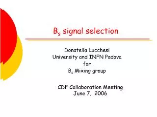
DSP. Digital Signal Products, Inc. Certified. Best Signal Selection. Operation

E N D
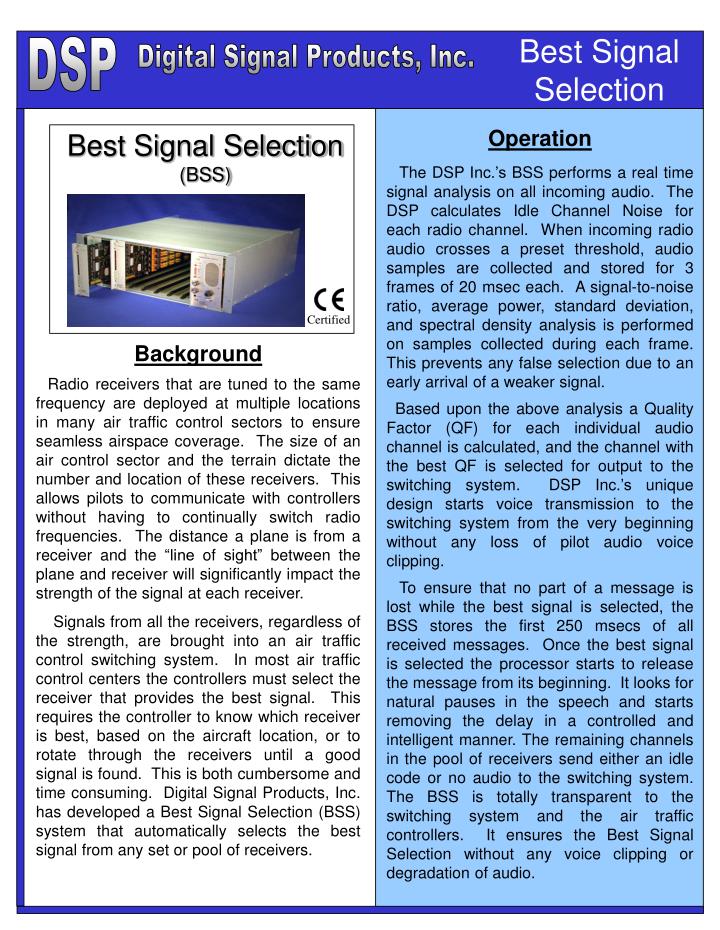
DSP Digital Signal Products, Inc. Certified Best Signal Selection Operation The DSP Inc.’s BSS performs a real time signal analysis on all incoming audio. The DSP calculates Idle Channel Noise for each radio channel. When incoming radio audio crosses a preset threshold, audio samples are collected and stored for 3 frames of 20 msec each. A signal-to-noise ratio, average power, standard deviation, and spectral density analysis is performed on samples collected during each frame. This prevents any false selection due to an early arrival of a weaker signal. Based upon the above analysis a Quality Factor (QF) for each individual audio channel is calculated, and the channel with the best QF is selected for output to the switching system. DSP Inc.’s unique design starts voice transmission to the switching system from the very beginning without any loss of pilot audio voice clipping. To ensure that no part of a message is lost while the best signal is selected, the BSS stores the first 250 msecs of all received messages. Once the best signal is selected the processor starts to release the message from its beginning. It looks for natural pauses in the speech and starts removing the delay in a controlled and intelligent manner. The remaining channels in the pool of receivers send either an idle code or no audio to the switching system. The BSS is totally transparent to the switching system and the air traffic controllers. It ensures the Best Signal Selection without any voice clipping or degradation of audio. Best Signal Selection (BSS) Background Radio receivers that are tuned to the same frequency are deployed at multiple locations in many air traffic control sectors to ensure seamless airspace coverage. The size of an air control sector and the terrain dictate the number and location of these receivers. This allows pilots to communicate with controllers without having to continually switch radio frequencies. The distance a plane is from a receiver and the “line of sight” between the plane and receiver will significantly impact the strength of the signal at each receiver. Signals from all the receivers, regardless of the strength, are brought into an air traffic control switching system. In most air traffic control centers the controllers must select the receiver that provides the best signal. This requires the controller to know which receiver is best, based on the aircraft location, or to rotate through the receivers until a good signal is found. This is both cumbersome and time consuming. Digital Signal Products, Inc. has developed a Best Signal Selection (BSS) system that automatically selects the best signal from any set or pool of receivers.
BSS Specifications Configuration Specifications Other Related Products Digital Signal Products, Inc. Certified Voice Clipping – In some communication switches, there are call types where a caller will start speaking before the connection to the receiving position is complete. The Audio Clipping ASP prevents the loss of the initial portions of an incoming call when the connection times within the switch are too slow and up to 1 second of the message is lost. Digital Signal Products, Inc. provides both high quality products for communication systems as well as services for developing solutions for specific customer problems. DSP can help establish requirements, provide both a high level design and a detailed design that satisfy a set of requirements and, if desired, actually build and test products that conform to the design. The BSS system is housed in a 19-inch rack mountable chassis, and occupies only 7.0 inch rack space. The BSS design employs a fully modular approach, using state of the art Digital Signal Processors. Each BSS card contains the DSP and necessary circuitry to provide an interface for up to six radio receivers. Two BSS cards can be configured to interface up to twelve radio receivers in a given pool. Each BSS card works in an independent manner, and provides the necessary BSS function for the configured group. A total of eight such cards can be installed in a single chassis to provide a total of 48 radio interfaces. A minimum of two, and a maximum of twelve, radios can be grouped together in any given pool, providing an extremely flexible, efficient and economical design approach. Each radio group can work independently in Selective, Multicast or Simulcast mode of operation. Interface to the voice switching system can be a single input/output radio circuit, or multiple inputs/outputs per radio group, thus providing a very flexible design solution. For radio groups that use a combination of ground based and satellite base radios (backup circuits), echo problems encountered by the mobile users can be easily corrected. A digital audio delay equalization (400-500 ms) can be introduced in any number of transmit audio paths, so that all transmissions reach mobile users at approximately the same time. Continuous health check combined with a high reliability design, insures a trouble free operation in critical communications systems. One card slot is provided for power supply/Summary Alarm card. In case of a BSS card failure, pre-defined Rx/Tx channels are automatically selected. An audio and visual alarm status is also provided. Interconnect to the BSS chassis is done through a backplane that provides 25 pair Amp-Champ telephone connectors, using industry standard, readily available mass terminated telephone cables. The chassis can be powered from 110/220V AC or –48V DC. To prevent any ground noise or hum interference all discrete inputs are optically coupled, and outputs are dry contact closures. A selected channel can be monitored using an audio interface located on the power supply card. Input/Output Impedance: 600 Ohms, balanced, transformer coupled to reduce hum and noise Input Level: -39 to + 8 dBm (nominal –6 or 0 dBm) Overall Gain: +/- 2 dB Frequency Response: 300-3000 Hz +/- 2 dB with-respect-to 1004 Hz Adjustments: None Required Distortion: 2% Maximum Coding: PCM, mu-law, 64 Kbits/s Voting Threshold Between Signals: 3 dB maximum VOX Threshold: -36 dBm with 3 dB of hesterisis Unselected Channel Rejection: Better than 60 dB Idle Channel Noise Output: 20 dBmCO Voting Delay: 150-200 msec Selection Hesterisis: 0-20 seconds, switch selectable AGC Range: +/- 8 dB with respect to selected input range Tone Notching and Automatic Gain Control (AGC) – Air Traffic Controllers have identified two significant problems in many current voice switches: high frequency tones accidentally induced into their headsets, and improper balancing of volume of incoming calls. DSP has developed an Audio Signal Processor (ASP) that can remove two extraneous tones simultaneously in less than 70 msec without degrading the quality of the incoming signal. The same ASP also adjusts all incoming calls to a volume that is selected by the air traffic controller. Radio Control Equipment (RCE) – DSP has developed an RCE that provides full duplex voice and data communications between a control site and a remote site over unconditioned telephone lines and satellite links. The control end modem trains the remote end modem to achieve the highest possible data transmission rate. The operator voice bandwidth is 300-3000 Hz end-to-end. The design employs speech encoding at 8 Kbits/s. Digital Signal Products, Inc. 21400 Ridgetop Circle, Suite 210, Dulles, VA 20166 Rev. A Jan, 03 Phone: (703) 654-7581 Fax: (703)654-7583 E-Mail: dsp@imcva.com