Download
1 / 12
130 likes | 231 Views
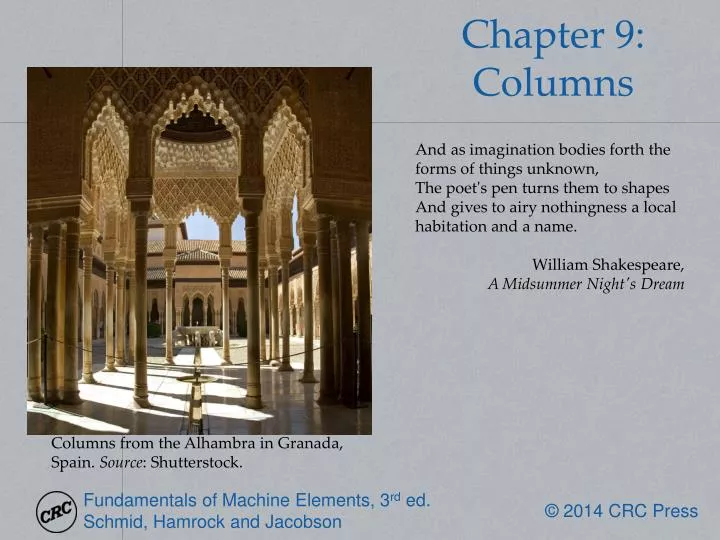
And as imagination bodies forth the forms of things unknown, The poet's pen turns them to shapes And gives to airy nothingness a local habitation and a name . William Shakespeare, A Midsummer Night's Dream. Chapter 9: Columns.

E N D
And as imagination bodies forth the forms of things unknown, The poet's pen turns them to shapes And gives to airy nothingness a local habitation and a name. William Shakespeare, A Midsummer Night's Dream Chapter 9: Columns Columns from the Alhambra in Granada, Spain. Source: Shutterstock.
Equilibrium Regimes Figure 9.1: Depiction of equilibrium regimes. (a) Stable; (b) neutral; (c) unstable.
Example 9.1 Given: A simple pendulum (Fig. 9.2) in which a ball is hung by a thin wire and is acted on by gravitational acceleration. Find: Is the system's equilibrium neutral, stable, or unstable? Solution: The force restoring the ball to the center position (θ= 0) is P = mag sin θ. From simple harmonic motion Combining gives For any angle θ, the angular acceleration d2θ/dt2has the opposite sign from θfor –π ≤ θ ≤ π. Thus, the ball will always return to the center position (θ= 0), implying that stable equilibrium prevails. Figure 9.2: Pendulum used in Example 9.1.
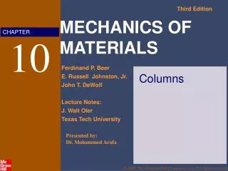
Column Euler buckling load: Associated critical stress: Critical slenderness ratio: Johnson Equation: Figure 9.3: Column with pinned ends. (a) Assembly; (b) deformation shape; (c) load acting.
Column Effective Length Table 9.1: Effective length for common column end conditions.
Buckling Figure 9.5: Normal stress as function of slenderness ratio obtained by Euler, Johnson, and AISC equations, as well as yield strength. Figure 9.4: Buckling of rectangular section.
Design Procedure 9.1: Selecting a Buckling Equation Often, one needs to design a column to support a given load, and constraints such as material, column length, etc, may be specified. It is often not clear beforehand whether a column will buckle according to the Euler or Johnson equations. The following procedure is useful in these cases: Assume that the column buckles according to Eq. (9.7), or that it encounters Euler buckling. Use this equation to determine the column's geometry. Calculate the critical slenderness ratio from Eq. (9.15) and (9.18), namely Calculate the slenderness ratio of the column from C=le/rg, where rgis given by Eq. (4.14) as If C ≥ Cc, then the column is indeed described by the Euler equation and the cross section calculated in step 1 is applicable. If C< Cc, the Johnson equation [Eq. (9.16)] must be used to determine the column geometry. Note that an equally useful design rule can be derived where the Johnson equation is assumed to be correct, and the Euler equation is used otherwise.
Example 9.3 Results Table 9.2: Summary of results for Example 9.3 Figure 9.6: Cross-sectional areas, drawn to scale, from the results of Example 9.3, as well as critical buckling load for each cross-sectional area.
AISC Buckling Criteria Elastic buckling: Inelastic buckling: Where Note: Not a prediction of buckling load, but rather a design framework for steel columns.
Eccentric Column Secant equation: Figure 9.7: Eccentrically loaded column. (a) Eccentricity; (b) statically equivalent bending moment; (c) free-body diagram through arbitrary section.
Eccentric Column Stresses Figure 9.8: Stress variation with slenderness ratio for five eccentricity ratios, for structural steel with E= 207 GPa and Sy= 250 MPa.
Crane Boom Figure 9.10: Illustration of a boom segment. A typical box boom consists of larger tubes or angle channels at the corners, supported by smaller braces or cords along the length. Boom segments are available in lengths ranging from 3-12 meters. Source:Courtesy of Manitowoc Co. Figure 9.9: Schematic illustration of a Manitowoc 4100W crane, showing the lattice boom, outriggers, and load and gantry lines. Source:Courtesy of Manitowoc Co.