Download

1 / 33
330 likes | 349 Views
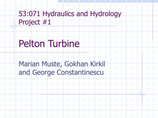
Nozzles & Jets for Pelton Wheels. P M V Subbarao Professor Mechanical Engineering Department. A Special Device to implement Pure Momentum based Energy Exchange……. Key Parts of Pelton Turbine. p atm. H. Design Of Intake for High Release of Power. Multi Jet Distributors for Pelton Wheels.

E N D
Nozzles & Jets for Pelton Wheels P M V Subbarao Professor Mechanical Engineering Department A Special Device to implement Pure Momentum based Energy Exchange…….
patm H Design Of Intake for High Release of Power
Discharge Distribution And Flow Energy Losses In the Distributor Q/QBEP
CFD Analysis of Free Jets & Flows In Air A Consultancy Project Sponsored By BHEL, Bhopal 2008 -- 2009
Governing Differential Equations • The set of governing equations solved were primarily the continuity and the momentum equations. • These basic equations in Cartesian coordinate system for incompressible flows are given below,
Exit Velocities The area averaged values for the various critical sections are listed below, Inlet : 20.77 ms-1 Outlet 1 : 25.37 ms-1 Outlet 2 : 18.13 ms-1 Outlet 3 : 17.05 ms-1 Outlet 4 : 16.91 ms-1 Outlet 5 : 15.22 ms-1 Outlet 6 : 9.75 ms-1
Feedback • It is evident from the area averaged values of velocity and the mass fluxes at the outlet that the flow distribution is not exactly uniform. • The flow at outlets 2, 3, 4, 5 is almost equal, however, flow at outlet -1 is high and outlet -2 is low. • The uniformity of flow distribution may be restored by employing variable openings using the spears provided inside the injection nozzle along with possible alterations in the rate of curvature of distributor especially in the region of outlet-6.
Closing Remarks : Multi Jet Pelton Wheel • Higher rotational speed • Smaller runner • Simple flow control possible • Redundancy • Can cope with a large range of flows But • Needs complex manifold • May make control/governing complex
A Complex Engineering Micro Alternate To Simple Gigantic Natural System
Simplification of Nozzle Shape b a d0 djet,VC The nozzle and spear are perfectly streamlined to reduce friction losses and achieve perfect circular jets.
Geometrical Relations for Nozzle The values of α varies between 20 to 30° whereas β varies from 30 to 45°.
Industrial Correlations for Jet Area variation with stroke Optimal value of Outlet jet area, ao s is the displacement of spear
Discharge through a Spear Nozzle if ao is the jet area at nozzle outlet section and knowing that this is dependable on the stroke s of the needle tip, the water velocity for this section is: Then, the corresponding flow rate is:
Geometrical Relations for Nozzle 1.1dO – 1.3dO 2dO – 2.4dO dO 0.8dO – 0.9dO 1.2dO – 1.4dO 5dO – 9dO
Performance Analysis of Nozzle-Spear Valve Ideal Nozzle-spear Valve: Along flow direction Real Nozzle-spear Valve:
Acceptable Performance of Nozzle Jet carrying a discharge of Q to deliver a power P To generate a discharge of Q, we need a least jet diameter of
The Diameter of Jet before Reaching Bucket Diameter of the Jet at the outlet, do It is important to find out the VC and outlet jet diameters/areas