Download
1 / 17
170 likes | 666 Views
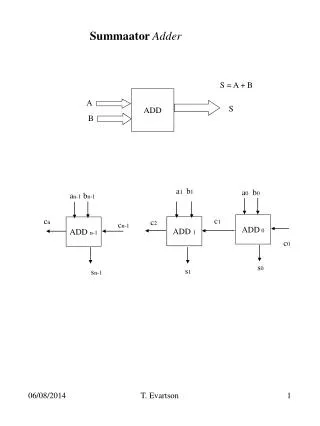
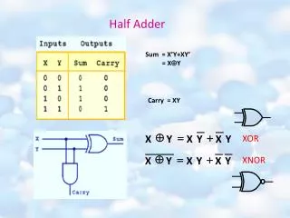
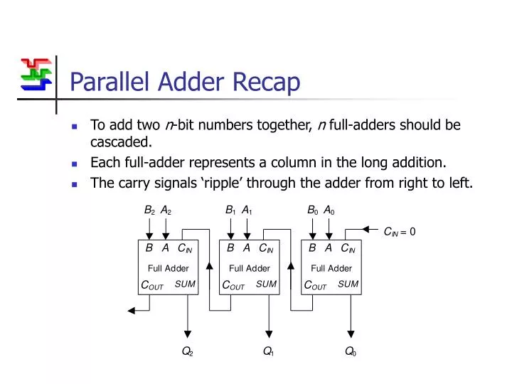
Parallel Adder Recap. To add two n -bit numbers together, n full-adders should be cascaded. Each full-adder represents a column in the long addition. The carry signals ‘ripple’ through the adder from right to left. Propagation Delay.

E N D
Parallel Adder Recap • To add two n-bit numbers together, n full-adders should be cascaded. • Each full-adder represents a column in the long addition. • The carry signals ‘ripple’ through the adder from right to left.
Propagation Delay • All logic gates take a non-zero time delay to respond to a change in input. • This is the propagation delay of the gate, typically measured in tens of nanoseconds. 1 0 X Y X 1 0 Y time
t = 0, A & B change t = 30 ns, Adder 0 outputs respond t = 60 ns, Adder 1 outputs respond t = 90 ns, Adder 2 outputs respond Carry Ripple • A and B inputs change, corresponding changes to CIN inputs ‘ripple’ through the circuit. B A B A B A 2 2 1 1 0 0 C = 0 IN B A C B A C B A C IN IN IN Full Adder Full Adder Full Adder C C C SUM SUM SUM OUT OUT OUT Q Q Q 2 1 0
Carry-Look-Ahead • The accumulated delay in large parallel adders can be prohibitively large. • Example : 16 bits using 30 ns full-adders : • Solution : Generate the carry-input signals directly from the A and B inputs rather than using the ripple arrangement.
B A CIN B A CIN B A CIN COUT SUM COUT SUM COUT SUM Designing a Carry-Look-Ahead Circuit B2 A2 B1 A1 B0 A0 CIN Carry-look-ahead logic Q2 Q1 Q0
A0-3B0-3CIN 4-bit adder COUTS0-3 A0-3B0-3CIN 4-bit adder COUTS0-3 Practical Carry-Look-Ahead Adder • The complexity of each CIN term increases with each stage. • To limit the number of gates required, a compromise between carry-look-ahead and ripple carry is often used. • Example : 8-bit adder using two four bit adders with carry-look-ahead.
1 1 0 1 0 0 0 1 0 (COUT = 1) + Overflow • What happens when an N-bit adder adds two numbers whose sum is greater than or equal to 2N ? • Answer: Overflow. • Example: 6+4 using a three-bit adder. (6)10 = (110)2 and (4)10 = (100)2
Modulo-2N Arithmetic • In fact, the addition is correct if you are using modulo-2N arithmetic. • This means the output is the remainder from dividing the actual answer by 2N. • An N-bit adder automatically uses modulo-2N arithmetic. • Example : 3-bits -> modulo-8 arithmetic
Modulo-8 arithmetic Example Sums 7 0 6 1 - + 5 2 4 3 Using Modulo-2N Arithmetic Conventional arithmetic - + 0 1 2 3 4 5 6 7 Subtracting 2 is equivalent to adding 6 Subtracting x is equivalent to adding 8-x
Two’s Complement • Using N bits, subtracting x is equivalent to adding 2N-x. • This implies that the number –x should be represented as 2N-x. • NB. To avoid ambiguity, when using signed binary numbers, the range of possible values is: • 3 bit example:
+ 1 0 1 1 1 1 1 1 1 0 (carry bits) 0 1 0 (sum bits) Signed Arithmetic • Binary arithmetic rules are exactly the same. • Now, however, overflow occurs when the answer is bigger than 3 or less than -4 111 000 Example: 3 - 1 -1 0 (3)10 = (011)2 (-1)10 = (111)2 110 001 -2 1 - + 2 -3 010 101 -4 3 011 100
Signed and Unsigned Numbers • All arithmetic operations can be performed in the same way regardless of whether the inputs are signed or unsigned. • You must know whether a number is signed or unsigned to make sense of the answer.
1 1 1 1 1 1 1 1 (2N-1 = 255) 0 0 1 0 1 1 0 1 (45) 1 1 0 1 0 0 1 0 (difference, each bit is complemented) - + 0 0 0 0 0 0 0 1 1 1 0 1 0 0 1 1 (211 = 256 – 45) Two’s Complement Conversion • A quick way of converting x to 2N-x is to complement all the bits and add one. • Why does this work ? Eg. N = 8 and x = (45)10 = (00101101)2
B A B A B A 2 2 1 1 0 0 C = 1 IN B A C B A C B A C IN IN IN Full Adder Full Adder Full Adder C C C SUM SUM SUM OUT OUT OUT Q Q Q 2 1 0 A Binary Subtraction Circuit To calculate A-B, all the bits in B must be complemented and an extra one added using CIN
Comparison • Whenever the result of an addition passes zero, a COUT signal is generated. • This can be used to compare unsigned numbers. COUT generated 7 0 6 1 + 5 2 4 3
Zero Flag • NORing the result bits together tests whether all the bits are low – i.e. the result is zero. • The resulting signal (or flag) is high only when A = B.
Summary • Carry-Look-Ahead • The speed of the parallel adder can be greatly improved using carry-look ahead logic. • Subtraction • An adder can be simply modified to perform subtraction and/or comparison. • Next Time • Circuits that can either add or subtract… and more.