Download
1 / 33
350 likes | 561 Views
A.G.Baiju. DIGITAL CONTENT MANAGEMENT IN TELEVISION BROADCASTING. Topics …. What is Television. Images - Black , White and Shades of Grey Colour - Hue & Saturation Sound - Audio Information Data - Teletext & Other Data Synchronisation - Specifies the Timing

E N D
A.G.Baiju DIGITAL CONTENT MANAGEMENT IN TELEVISION BROADCASTING
What is Television • Images - Black , White and Shades of Grey • Colour - Hue & Saturation • Sound - Audio Information • Data - Teletext & Other Data • Synchronisation - Specifies the Timing • Transport System - Gets the Above to your TV • India Adopted PAL (B) Standard
Introduction to VideoPersistence of Vision • The persistence of vision theory states that the human eye holds a still image for a fraction of a second, remaining on the retina long enough to blend with the next image. • Film displays 24 still images each second (frames per second or fps).
Frame Rate • A Frame represents a complete TV picture • Our analog TV Frame consists of 625 lines. • A Frame is usually comprised of 2 Fields each containing 1/2 the picture information • Our system has a Frame rate of 25 Hz • The Field rate is 50 Hz • Interleaving the Fields reduces flicker.
Interlaced scanning • To reduce the perceived screen flicker (25 Hz) on a television, a technique called 'interlacing' is employed. • Interlacing divides each video frame into two fields; the first field consists of the odd scan lines of the image, and the second field of each frame consists even scan lines.
Color Signal Components • Three RGB signals are converted into Luminance Y, and color difference signals using simple mathematical relation • Y=0.3R+0.59G+0.11B, Luminance Signal • U or Cb = 0.493(B-Y) Color Difference Signals • V or Cr = 0.877(R-Y)
Digital System - Benefits • It is highly flexible and versatile. • No quality degradation with multiple usage. • Highly reliable, efficient and nondestructive editing • Complete automation is possible. • Excellent signal to Noise Ratio - better than 90 dB. • It is possible to use compression technique. This results in bandwidth saving. • Tremendous benefits in the areas of post-production, archiving and multi-generation. • Hard disk recording facilitates random access. • Centralised storage system can be provided.
Digital Video (SDI) In a 720X 576 pixel PAL SD frame : • 4.4.4 : Y, Cr and Cb sampled equally • 4.2.2 : In a line, 720 samples for Y and 360 samples each for Cr and Cb • 4.1.1 : In a line, 720 samples for Y and 180 samples each for Cr and Cb • 4.2.0 : In a line, 720 samples for Y and 360 samples each for Cr and Cb but Cr and Cb samples are taken only from alternate lines
4.2.2. Digital Video Analog to Digital conversion through sampling, quantizing and coding • Y sampled at 13.5 Mhz (4X 3.375) • Cb, Cr sampled at 6.75 Mhz With 10 bit coding : (13.5+6.75+6.75)10 = 270 Mbps
Embedded Audio Sampled at 48 kHz, 24-bit (20-bit in SD, but extendable to 24 bit) PCM audio is stored, in a manner directly compatible with the AES3 digital audio interface. These are placed in the (horizontal) blanking periods, when the SDI signal carries no useful signal, since the receiver generates its own blanking signals from the TRS.
Need for Compression of Data • 270 Mbps bit rate require high bandwidth of nearly 180Mhz for transmission • Satellite Transponder BW is just 36 Mhz • Data storage capacity is very limited
Source Coding • SPECTRAL REDUNDANCY • SPATIAL AND TEMPORAL REDUNDANCY. • ENTROPY REDUNDANCY. • PSYCHO VISUAL REDUNDANCY
MPEG: Motion Picture Experts Group • MPEG-1 (1992) • Compression for Storage • 1.5Mbps • Frame-based Compression • MPEG-2 (1994) • Digital TV • 6.0 Mbps • Frame-based Compression • MPEG-4 (1998) • Multimedia Applications, digital TV, synthetic graphics • Lower bit rate • Object based compression
Recording : Video Tape Formats • Video tape made today’s TV possible • Non-simultaneous transmission of events • Formats: • DV, DVCAM digit., 4:1:1, 8bit, 5:1 DV, 25 Mb/s • DVCPRO-50 digit., 4:2:2, 8bit, 3.3:1 DV, 50 Mb/s • Betacam SX digit., 4:2:2, 8bit, 10:1, Studio-MPEG-2 • Dig. Betacam digit., 4:2:2, 10bit, 2:1
Recording : HDD - RAID • Stands for Redundant Array of Independent Disks. • It’s a technology that enables greater levels of performance, reliability and/or large volumes when dealing with data. • By concurrent use of two or more ‘hard disk drives’. • Mirroring, Stripping (of data) and Error correction techniques combined with multiple disk arrays give you the reliability and performance.
RAID 5 • RAID 5 implements data stripping with distributed parity • Pro: Fastest read speed, decent write speed. Good protection. Cost effective = commercial success • Con: Most complex design. Difficult to rebuild data.
RAID 6 • RAID 6 implements data stripping with dual error protection • Pro: Excellent protection, can sustain multiple hits. • Con: Complex to implement.
BENEFITS OF A NETWORK • Information sharing: Authorized users can use other computers on the network to access and share information and data. This could include special group projects, databases, etc. • Hardware sharing: One device connected to a network, such as a printer or scanner, can be shared by many users. • Software sharing: Instead of purchasing and installing a software program on each computer, it can be installed on the server. All of the users can then access the program from a single location. • Collaborative environment: Users can work together on group projects by combining the power and capabilities of diverse equipment.
Star topology A star topology is designed with each node (file server, workstations, and peripherals) connected directly to a central network hub or concentrator. Data on a star network passes through the hub or concentrator before continuing to its destination. The hub or concentrator manages and controls all functions of the network. starstructure • Advantages of a Star Topology • Easy to install and wire. • No disruptions to the network then connecting or removing devices. • Disadvantages of a Star Topology • Requires more cable length than a linear topology. • If the hub or concentrator fails, nodes attached are disabled.
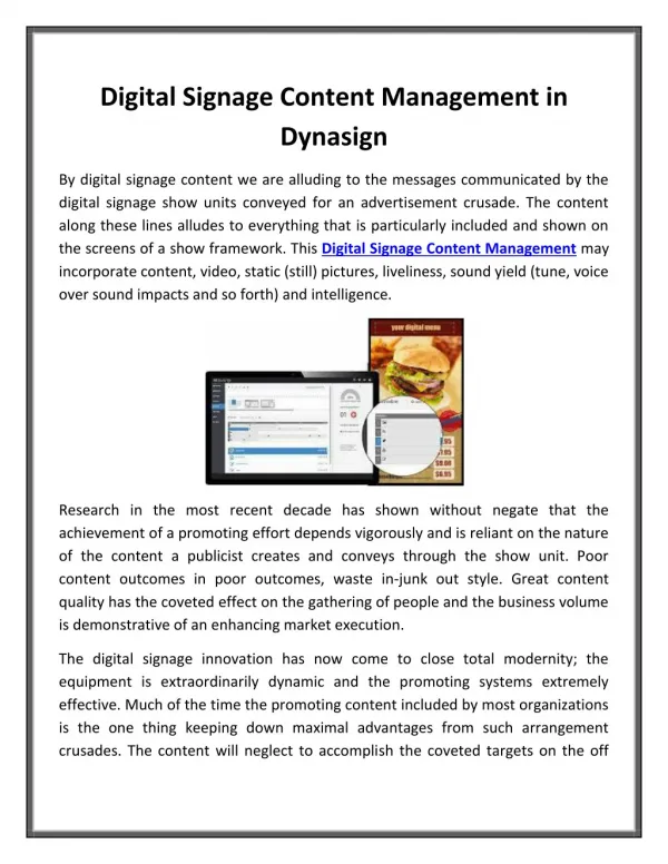
Media Asset Management • Efficient long term utilisation of media assets • Digitize content in to multi format • Optimise work flow processes • Archive • OPAC (Online public access catalog search) • federated search • Link with cloud based services • Cost estimation • Efficient revenue generation
INTERNET MLMS Server Video Server Metadata Flow Tape Information With Program Details Start Point / End Point Type Resource Manager Browser based Search Engine with Thumbnail Preview using online public access catalog search method
Video Server MLMS Server Video Server MLMS Server Video Server MLMS Server Video Server MLMS Server Multi-Location Central Access West Zone East Zone Federated Search North Zone South Zone