Download
1 / 12
190 likes | 1.72k Views
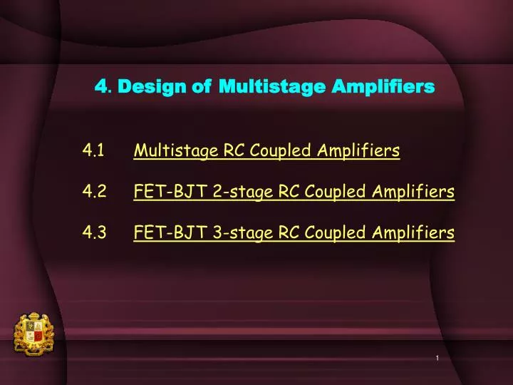
4 . Design of Multistage Amplifiers. 4.1 Multistage RC Coupled Amplifiers 4.2 FET-BJT 2-stage RC Coupled Amplifiers 4.3 FET-BJT 3-stage RC Coupled Amplifiers. 4.1 Multistage RC Coupled Amplifiers.

E N D
4. Designof Multistage Amplifiers 4.1 Multistage RC Coupled Amplifiers 4.2 FET-BJT 2-stage RC Coupled Amplifiers 4.3 FET-BJT 3-stage RC Coupled Amplifiers
4.1 Multistage RC Coupled Amplifiers Note that in multistage amplifiers, (a) VO of the preceding stage becomes Vin of the following stage, example VO1=Vin2, (b) Rin of the following stage becomes RL of the preceding stage, example RL1=Rin2, (c) Overall gain is the product of gain of every stage. So the design depends upon the available data between stages. For example, without knowing Rin2 of the second stage, design is not possible to meet the voltage gain of the first stage.
4.2 FET-BJT 2-stage RC Coupled Amplifiers Design Example Draw the circuit and design the following 2-stage RC coupled amplifier. First stage is a JFET self-bias CS amplifier circuit. Design the parameters of the JFET( IGSS, IDSS and VP,)and VDD for requiredRG=20MW , Av = -12 and RD = RL1 = Rin2 =2kW. Assume VD=VDD/2=10V The above FET amplifier is RC coupled to a second stage (CE) amplifier circuit whose specifications are: b=200, VCC = 10V, optimum output voltage design, RC= RL = 2kW, RE= 0.4kW, Design bias resistances R1 and R2. Overall performance # What is the total voltage gain from the input of the first stage to the output of the second stage? # Find undistorted output voltage swing at second stage output and # The possible maximum input voltage at the first stage.
Draw Circuit to be designed Self Bias CS Amp. RG=20MW , Av = -12 and RD = RL1 = Rin2 =2kW. Assume VD=VDD/2=10V CE Amp.b=200, VCC = 10V, optimum output voltage design, RC= RL = 2kW, RE= 0.4kW
Because RL1 = Rin2 =2kW is available, design is possible for the first stage voltage gain and also design of RB2 of the second stage. Therefore the design can start with the first FET stage as follows; Given; CS Amp. RG=20MW , Av = -12 and RD = RL1 = Rin2 =2kW. Assume VD=VDD/2=10V
Because Rin2 =2kW is available, design is possible for the RB2 of the second stage. Given; CE Amp. b=200, VCC = 10V, optimum output voltage design, RC= RL = 2kW, RE= 0.4kW
Overall performance # What is the total voltage gain from the input of the first stage to the output of the second stage? # Find undistorted output voltage swing at second stage output and # The possible maximum input voltage at the first stage. 10V 10V 2k 73k 2k 5.88V(pp) 4.24mV(pp) 19k 2k 20MW 71W 0.4k Av1=-12 AvT=1357 Av2=-113
SF Amp. To provide high Rin3 and Voltage divider bias to provide large output voltage swing to drive RS3= RL = 1000W Self bias CS Amp. To provide very high Rin but small signal Vo since it is a preamplifier stage Take AV = -12 CE Amp. For high Av Take RC=2kW Rin3 = 20kW For maximum voltage transfer from 2nd stage to 3rd stage 4.3 FET-BJT-FET 3-stage- RC Coupled Amplifiers To design an amplifier having (a) very high Rin & (b) very high voltage gain & (c) very large signal output voltage swing driving a very low load resistance, following stages are selected.
RG RD = RL RS VDD Draw and Design RG , RS , RD = RL and VDD of the first stage JFET self-bias CS amplifier circuit. FET data is given as IGSS=300nA, IDSS=5mA and VP=-3V, The required specification is VD=VDD/2 and Av = -12
RG R12 R22 Vo2 (pp) Av2 Draw and design second stage (CE) amplifier circuit Given specifications are: b= 200, VCC = 10V, RC= 2kW, RL= 20 kW , RE = 0.4kW, Rin= 10.3kW. Design bias resistances R1and R2, # find voltage gain,and undistorted output voltage swing of this stage.
Check Rin3 < 300k with IGSS=1mA VDD3 R13 R23 Vin1 (pp) AvT Ro < 1k so it can drive RL=1kW load easily Draw and design R13 , R23 , and VDD3 of the third stage JFET voltage-divider bias SF amplifier circuit if the FET data is IGSS=1mA, IDSS=10mA and VP=-3V, The required specification is VS=VDD/2 to drive a load of RS = RL 1kW # Find Ro of your amplifier and # maximum input voltage at the first stage.
Vin1 (pp) AvT Ro < 1k so it can drive RL=1kW load easily 50.65V 10V 10V 2kW 10.13kW 16.49kW 48.8kW 3 mV 5V 33.9kW 1MW 1kW 3.33kW 1kW 360W 0.4kW Av3=0.825 Av2=-164 Av1=-12 AvT=1623.6 Overall performance # Find AvT of your amplifier and # maximum input voltage at the first stage and # check Ro whether it can drive RL=1kW load easily.